A PVD coating can improve a mold insert’s surface performance while making its fit worse. A film measured in micrometres may consume a meaningful share of a precision clearance. If the underlying steel is unstable, the surface is damaged or the failure is mechanical, choosing a harder coating may not solve the problem.
The useful question is not simply “Which coating is best?” It is: which surface needs protection, against which failure mechanism, and what must remain true after coating? This guide explains how tooling engineers and buyers can select PVD coatings for mold inserts, plan dimensional allowances and request evidence that supports release.
Approve a coating only after five decisions are closed: the failure mechanism, substrate and thermal compatibility, coated and masked zones, final dimensions, and acceptance evidence. Specify thickness per surface—not just a coating name—and distinguish deposition temperature from service temperature.
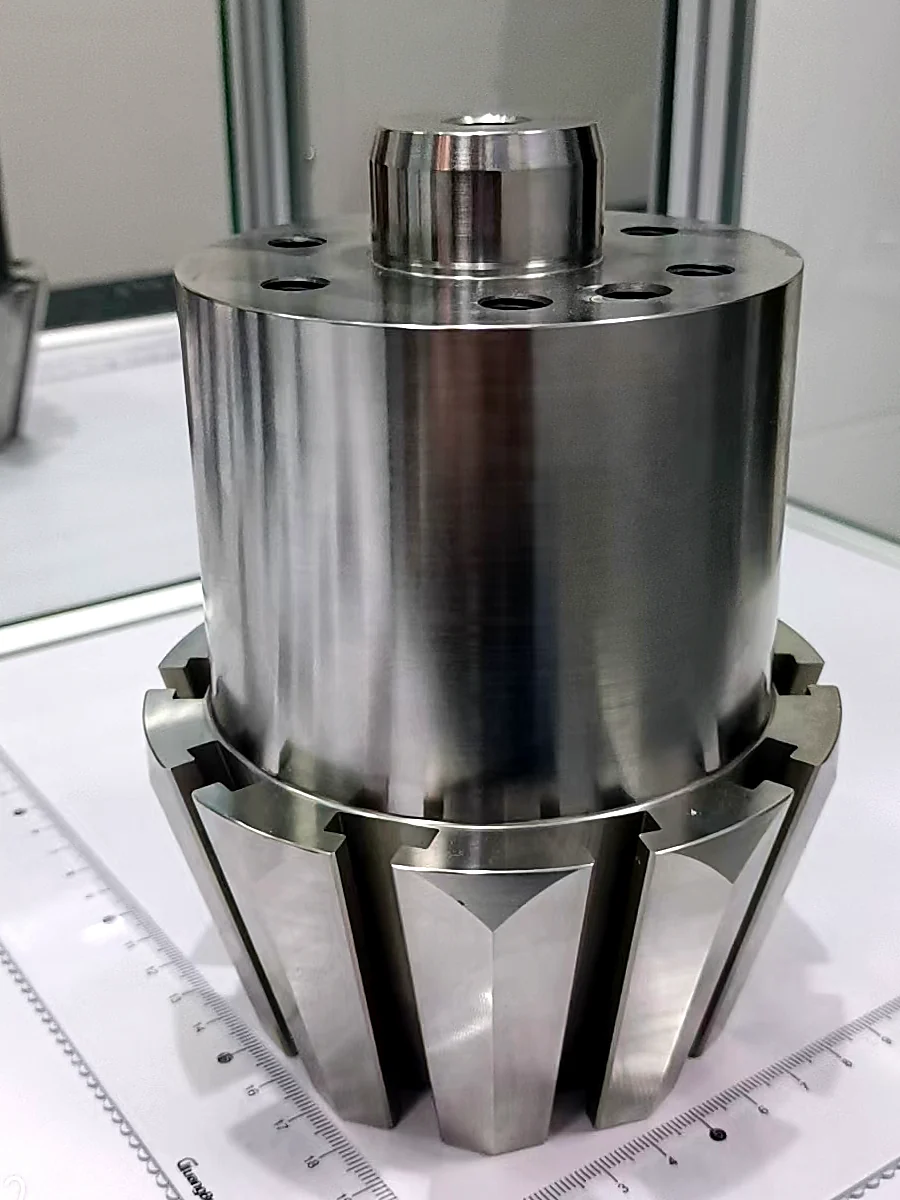
Start with the failure, not a coating catalogue
Different problems can produce similar complaints: sticking parts, frequent polishing, scratched surfaces or a short maintenance interval. Before selecting a film, retain photographs of the affected zone and record the resin grade, filler, cycle conditions, cleaning method, mating material and number of cycles at first deterioration.
Ionbond identifies abrasive, corrosive and frictional wear as important mechanisms in plastic molding. Its application guidance distinguishes glass-filled material wear, resin-related corrosive attack and friction during processing or ejection. These are supplier-reported application categories, not evidence that any one coating will solve all three on your tool. Ionbond plastic-molding guidance.
| Observed pattern | Investigate first | What to ask the coating provider |
|---|---|---|
| Directional wear in resin-contact zones | Filler abrasion, local flow and substrate condition | Which candidate has relevant wear evidence for this resin and surface? |
| Material transfer or scoring on sliding interfaces | Galling, alignment, contact pressure, roughness and lubrication | Which side should be coated, and what counterpart finish is required? |
| Pitting or discoloration after production or storage | Resin chemistry, condensation, cleaners and steel selection | What corrosion evidence covers the actual exposure and coating defects? |
| Sticking without visible steel wear | Draft, texture, venting, cooling and ejection conditions | Can a surface treatment address release after those causes are checked? |
| Broken edges, bent cores or damaged shut-offs | Interference, impact, support, toughness and overload | Is coating appropriate at all before the mechanical cause is corrected? |
A useful purchase specification starts with the measured loss of function. “Reduce cleaning interruptions caused by deposit adhesion at zone F1” is more actionable than “apply the hardest coating available.” For precision mold inserts, a film should be selected as part of a working interface, not as an isolated hardness number.
Check the steel, heat treatment and surface together
PVD means physical vapor deposition, while DLC means diamond-like carbon, a family of carbon-based coatings. They are not competing categories: DLC can be deposited by PVD or plasma-assisted chemical vapor deposition (PACVD). Record the specific coating system, deposition method and provider’s process revision rather than treating “DLC” as a complete specification. Ionbond distinguishes these routes in its coating-technology overview.
The substrate must support the film under the actual contact load. Oerlikon’s component-coating handbook discusses substrate strength, thermal compatibility, cleanliness and the way thin coatings follow the existing surface. The engineering implication is important: a thin film is not a structural repair or a substitute for an appropriate base steel. Review the Oerlikon coated-components handbook with the provider for the selected system.
Keep three temperature questions separate:
- Deposition temperature: what thermal cycle will the component experience during preparation and coating?
- Steel compatibility: does the documented heat-treatment history permit that cycle without unacceptable softening or dimensional change?
- Service temperature: is the coating suitable for the temperatures and chemical exposure at the working interface?
For a concrete example—not a recommendation—Ionbond currently lists a process temperature of 160–250°C and a service temperature of 350°C for Ionbond 40. The two values answer different questions. Neither establishes compatibility with an unidentified steel or guarantees dimensional stability of a finished insert. Check the Ionbond 40 product data, then compare the proposed cycle with the actual steel and heat-treatment record.
Preparation is equally important. Uddeholm’s PVD guidance highlights the condition of active surfaces, grinding marks and damaged layers left by EDM. Its numerical roughness recommendations include cold-work applications; do not copy them unchanged onto a cosmetic injection-mold surface. Use the underlying principle—sound, appropriately finished steel—and agree application-specific limits. Uddeholm tool steels for PVD coatings.
If the insert is spark-eroded, define the condition to be supplied to the coater in the EDM process route. If it is polished or textured, specify which surfaces may be cleaned, blasted, honed or post-polished. An attractive coating over an unapproved substrate finish is not an acceptable shortcut.
Calculate what coating does to clearance
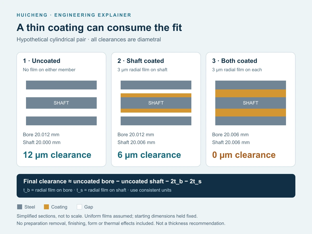
A coating grows from the surface on which it is deposited. For a cylindrical external feature with uniform radial thickness t, diameter increases by approximately 2t. A uniformly coated bore loses approximately 2t in diameter. These are geometric relationships, not promises of uniform deposition inside a real bore.
The same dimensional check applies to cylindrical interfaces on core pins and ejector sleeves when those surfaces are specified for coating. For a cylindrical sliding pair, let Db and Ds be the uncoated bore and shaft diameters, and tb and ts their respective radial coating thicknesses. If preparation and finishing do not otherwise change geometry:
Final diametral clearance ≈ Db − Ds − 2tb − 2ts
Worked example: a 12 µm clearance can disappear
Assume a shaft diameter of 20.000 mm and a bore diameter of 20.012 mm. Initial diametral clearance is 0.012 mm, or 12 µm. Coating the shaft alone with a uniform 3 µm radial film increases its diameter to 20.006 mm, leaving 6 µm clearance. If the bore also receives 3 µm on each internal wall, its diameter becomes 20.006 mm: nominal clearance is now zero.
Variation matters as much as the target. Holding those starting diameters fixed, a hypothetical 2–4 µm film on the shaft alone leaves 4–8 µm diametral clearance. Coating both members within that same range produces a calculated range from 4 µm interference to 4 µm clearance. Starting-part tolerances, form error and thermal effects would widen the real assessment further.
For a worst-case minimum-clearance check, use the smallest bore, largest shaft and largest permitted coating thickness on each member. Include preparation removal and post-coating finishing separately if they are part of the route. Do not assume a final polish removes the same amount everywhere.
For rectangular inserts, sum the growth on opposing faces when calculating width. For an inclined shut-off or freeform surface, evaluate the local normal direction and the actual mating geometry. Relate the allowance to the functional tolerance scheme; do not subtract a blanket value from every drawing dimension.
Specify coverage, masking and inaccessible regions
“Coat the whole insert” leaves essential interfaces undefined. Mark coated zones, protected datum and fitting surfaces, intentional fixture-contact areas, permitted boundary transitions and inspection locations on a controlled drawing.
PVD is generally a line-of-sight process, so recessed surfaces and internal features require a coverage review. Rotation helps expose surfaces but does not prove that every deep feature receives the specified thickness. The deposition and masking limitations depend on the selected route; use the actual geometry in the provider’s feasibility review rather than a universal bore-depth rule.
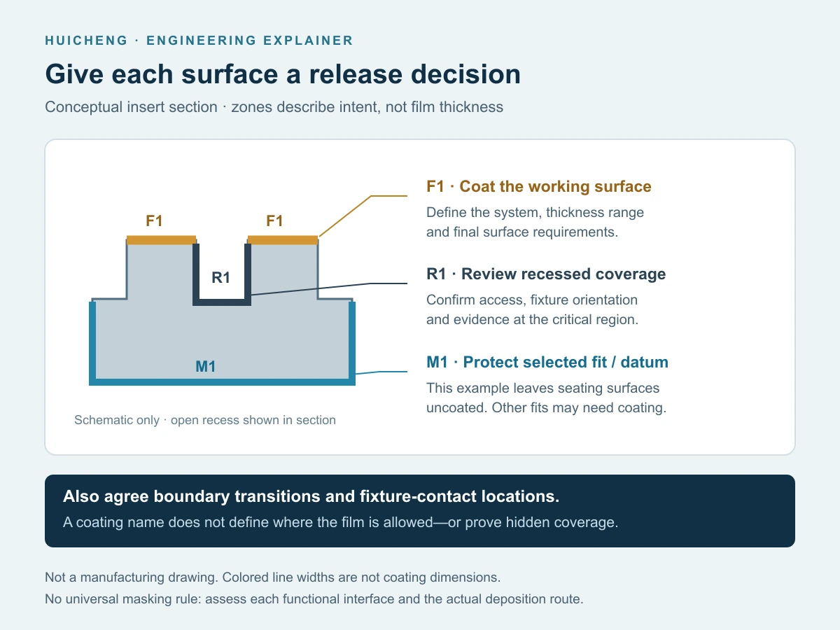
A replaceable insert may need a wear-resistant forming zone while its seating face and locating sides remain uncoated to preserve an existing pocket fit. On sliders, lifters and related moving components, a fitted sliding surface may itself require coating, in which case the final coated size must be designed into the fit. “Always mask the datums” is no more reliable than “coat everything.” Decide surface by surface.
For masked boundaries, agree the allowable transition position and whether a step, overspray region or bare strip is acceptable. Locate the transition away from critical sealing or sliding contact where practical. Confirm that a fixture contact will not land on a cosmetic or functional area.
Use five gates to authorize coating
These gates are an editorial planning checklist, not an industry certification. Each gate should have an owner and a recorded decision before the component leaves for coating.
- Failure gate: record the affected zone, failure mechanism and trial objective. If overload, interference or unstable processing remains unresolved, pause the coating decision.
- Substrate gate: approve the steel condition, heat-treatment history, surface preparation and permitted thermal cycle.
- Geometry gate: approve coated and masked zones, deposition access, fixture contacts and final dimensional requirements.
- Evidence gate: agree the thickness and adhesion methods, witness-sample arrangement, final inspection plan and acceptance criteria.
- Recovery gate: define whether stripping, re-polishing and recoating are permitted, who authorizes them and what must be remeasured.
A supplier’s capability to strip one coating from one material is not permission to repeat that cycle indefinitely on a precision insert. Keep a history of coating, removal and repair. If stripping or preparation changes a fitting surface, recalculate the remaining geometry before approving the next cycle.
Define what the inspection report must prove
The finished component and the coating process need complementary evidence. A certificate can identify a coating batch; it cannot, by itself, prove that every fitting face and inaccessible feature meets the drawing.
| Acceptance question | Evidence to request | Important limitation |
|---|---|---|
| Was the approved process used? | Coating designation, substrate IDs, batch record and agreed process statement | A trade name alone does not identify preparation or masking |
| Is thickness appropriate? | Method, locations, readings and permitted variation | A flat witness coupon does not prove thickness at a shadowed recess |
| Does the coating adhere? | Agreed test method, specimen condition and acceptance classification | Adhesion testing may damage the tested surface |
| Does the component still fit? | Final dimensions and datum-related inspection after all finishing | A pre-coating CMM report does not establish final coated size |
| Is the working surface acceptable? | Roughness or texture evidence, visual inspection and boundary review | Coating color and apparent gloss do not establish functional performance |
ISO 26443:2023 describes a qualitative Rockwell indentation method for evaluating adhesion of ceramic coatings within its scope; it is not suitable for elastic coatings on hard substrates. ISO 20502:2005 describes scratch testing of a coating–substrate system. Neither should be specified merely because it appears on a certificate: first establish method suitability and where testing can be performed without damaging a saleable functional surface. See the official scopes for ISO 26443:2023 and ISO 20502:2005.
If witness samples are used, specify how they represent the batch: material, hardness, preparation, position and exposure. Document the limitations of that representation. For the actual insert, connect final dimensions to the CMM inspection and datum plan, and define finish acceptance in the surface-finish specification.
Validate life improvement with a controlled trial
A claim such as “three times longer tool life” is meaningful only if the comparison uses a defined failure endpoint and comparable conditions. Distinguish fewer cleaning stops from less steel wear, better part release or longer time to repair; they may not improve together.
For a useful first trial, record:
- the baseline insert condition, resin and filler, process settings and cleaning practice;
- which surfaces and mating components changed;
- cycles or production time to a predefined inspection or maintenance trigger;
- part quality, dimensional trend and ejection behavior over the trial;
- coating condition, location of wear and observations after cleaning;
- stopping criteria for flaking, interference, abnormal force or unacceptable molded parts.
Compare cost per acceptable production interval, not coating price alone. Include preparation, transport, inspection, maintenance time, scrap and recovery. Do not extrapolate one successful trial to another resin, geometry or counterpart without reviewing the changed conditions.
RFQ checklist and drawing-note template
Add a coating schedule to the precision mold component RFQ:
- matched drawing/model revisions, component IDs and the failure being addressed;
- resin, filler, cleaning chemistry, operating temperature and mating material;
- steel grade, hardness, heat-treatment history and approved thermal exposure;
- specific coating designation and deposition route, or a request for justified alternatives;
- coated, masked, fixture-contact and coverage-review zones;
- thickness range per surface and final coated dimensions with datum references;
- surface preparation, edge condition and permitted post-coating finishing;
- inspection methods, locations, sample plan, report content and acceptance limits;
- permitted stripping/recoating route and the trial release criteria.
Template—replace every bracketed item before use:
Apply [approved coating/system] by [process] to zones [IDs]. Finished film thickness shall be [range] per specified surface, verified at [locations] by [method]. Protect zones [IDs]; boundary transition shall remain within [defined band]. Substrate preparation and maximum thermal exposure require approval against [material/heat-treatment record]. Dimensions identified [IDs] apply after coating and all permitted finishing. Supply [batch record, thickness report, agreed adhesion evidence and final dimensional report]. No stripping, blending or recoating without written approval.
This template intentionally has no default thickness, hardness or temperature. Those values belong to the specific coating–substrate–geometry combination. Include the drawing and coating schedule in your component enquiry to Huicheng for a manufacturing feasibility discussion; confirm the coating route, provider and validation responsibilities separately.
Frequently asked questions
Which PVD coating is best for a mold insert?
There is no universal best coating. Begin with abrasion, adhesion, corrosion or another defined failure, then check the substrate, geometry, temperature, counterpart and evidence. A material name or hardness value alone is not a selection method.
Does PVD coating change a precision fit?
Yes. An external diameter grows by approximately twice the uniform radial film thickness, while a uniformly coated bore shrinks by twice its film thickness. Include both mating members, thickness variation and final finishing in the clearance calculation.
Can a thin coating repair an oversized cavity or worn fitting surface?
Do not use a wear coating as an unqualified dimensional repair. Any intended buildup needs its own coverage, thickness, support, finishing and acceptance review. A coating selected for friction reduction is not automatically appropriate for restoring geometry.
Should PVD coating be applied before or after final polishing?
The substrate normally needs an approved finish before deposition. Some systems also use controlled post-treatment. Specify both stages and reverify final geometry and surface condition; do not assume that unrestricted polishing after coating is acceptable.
Can all deep slots and internal holes be coated uniformly?
Do not assume so. Coverage depends on the deposition route, opening geometry, orientation and fixturing. Ask the provider to confirm the critical internal zones and how their coverage will be demonstrated.
Is a coating certificate enough for release?
No. Match the certificate to the approved batch and system, then check the required thickness, adhesion evidence, masking, final dimensions and working-surface condition. Process documentation and finished-part acceptance answer different questions.
Source and scope note: Seven primary-source links appear beside the claims they support. Manufacturer examples describe their own systems, not Huicheng performance guarantees. The dimensional example and release checklist are original engineering explanations. This guide does not prescribe universal coating parameters or certify a component.