Sliders, Lifters & Complex Components
undercuts, angles, coordinated motion.
Huicheng manufactures mold sliders (滑块), lifter blocks (斜顶), angle pins, cam slides, gib surfaces and complex multi-component assemblies to controlled drawings. Precision CNC, EDM, grinding and fit verification support undercut formation, angled ejection and coordinated mold motion.
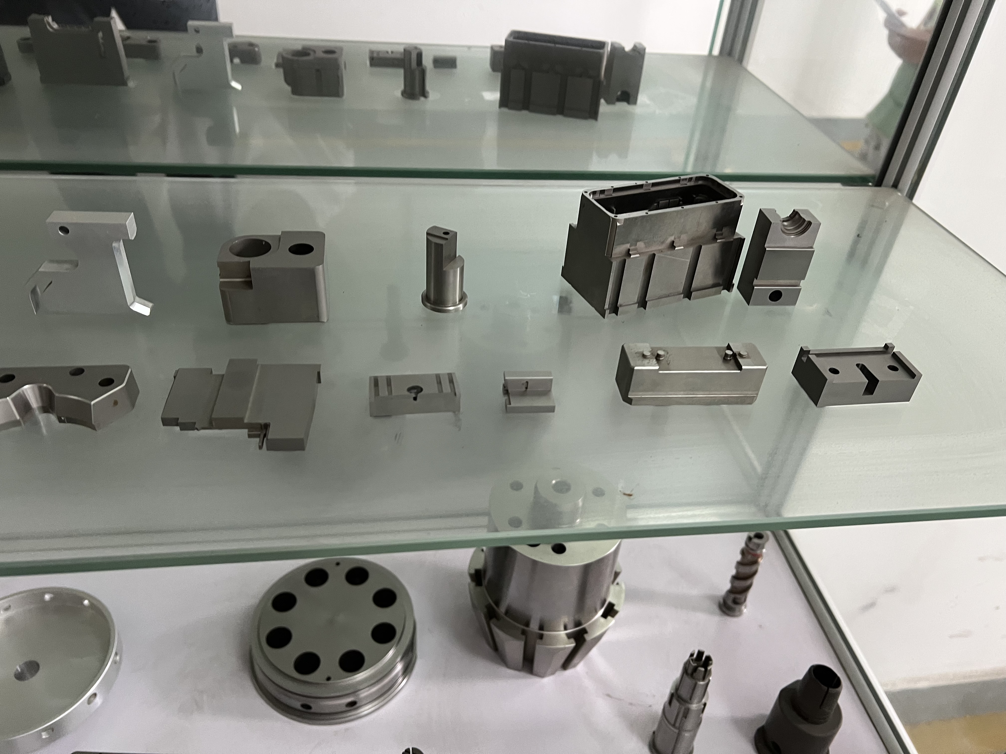
Sliders form undercuts.
Lifters eject at an angle.
Sliders are horizontal motion components that move perpendicular to the mold opening direction to form side undercuts, holes, threads or complex side-wall features. Lifters (also called angle pins or lifter blocks) move at an angle during mold opening to eject parts with angled features, ribs or undercuts that cannot be handled by straight ejection.
Slider and lifter manufacturing requires precision machining of gib surfaces (wear plates), angled cam surfaces, mounting interfaces and cavity detail. Because sliders and lifters must move smoothly under load and close repeatably to tight clearances, fit tolerance, surface finish, parallelism and angle accuracy are critical dimensions that must be verified as a coordinated assembly, not only as individual parts.
From simple slides
to multi-axis motion.
These photographs show representative slider and complex component work from Huicheng’s factory. Customer names, drawing numbers and dimensional values are not shown.
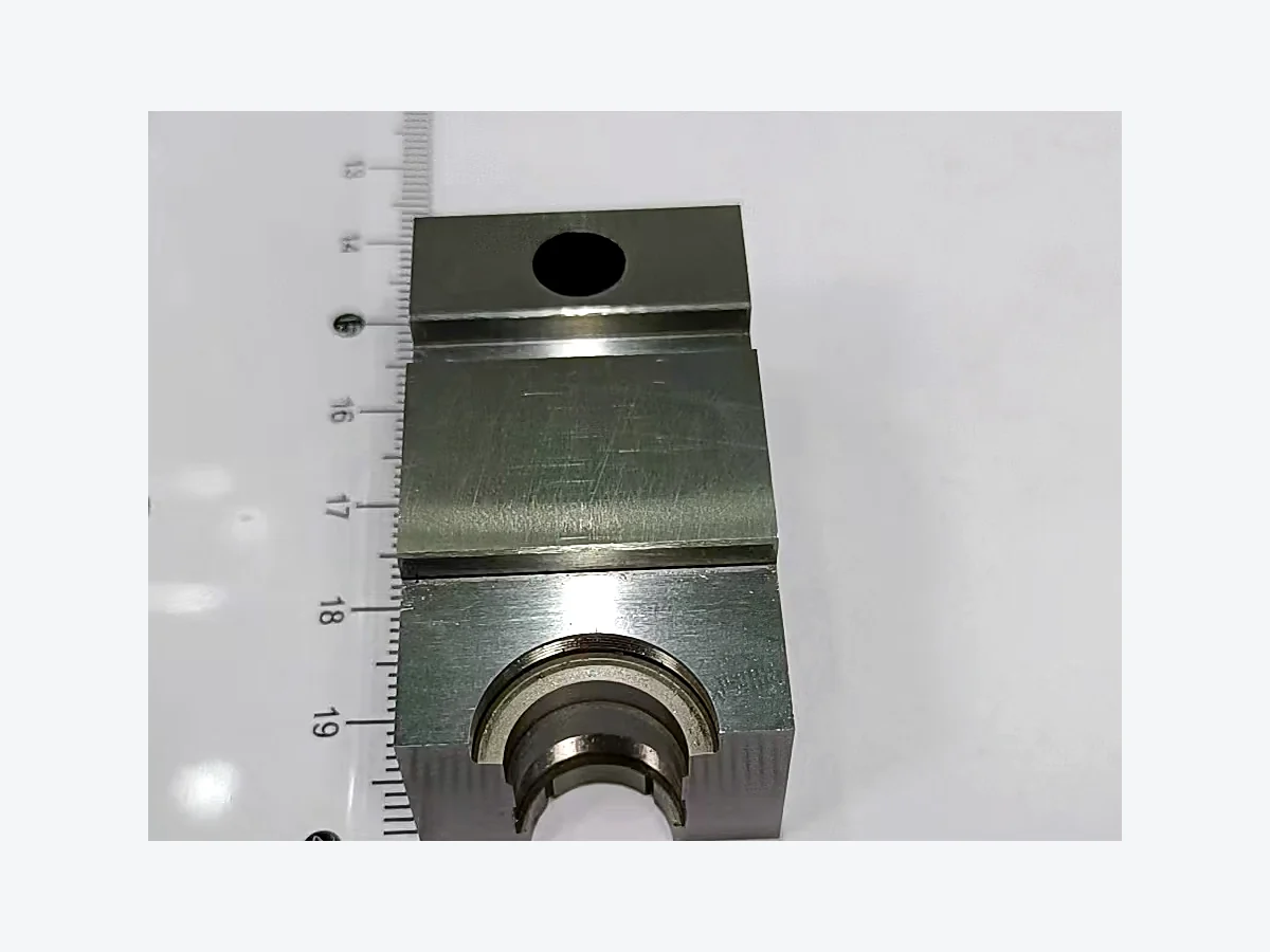
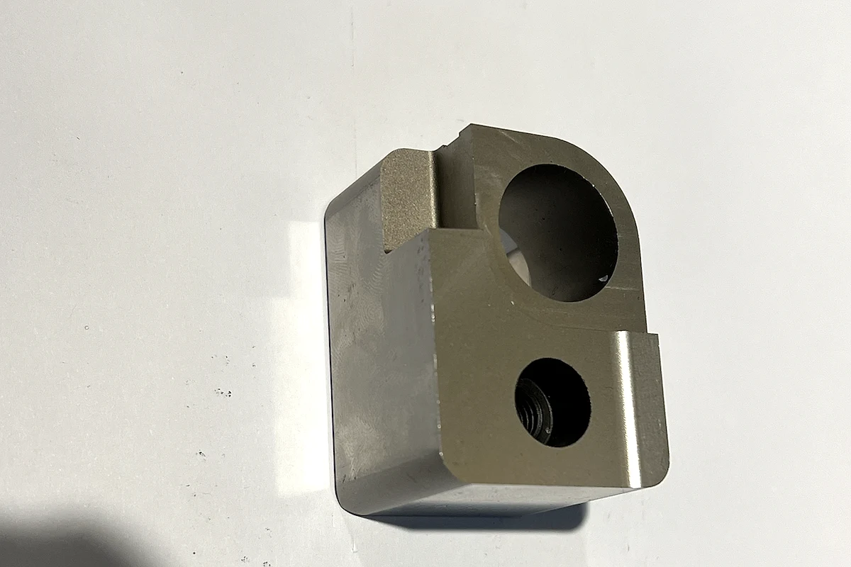
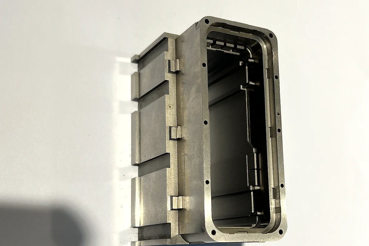
Representative work only. Customer drawings, names, dimensions and project identifiers are not shown.
Plan the assembly relationship
before machining individual parts.
Sliders and lifters are rarely independent components. The manufacturing route must coordinate datums, gib surfaces, cam angles, cavity detail and assembly fit across multiple mating parts.
Assembly and motion review
Confirm slider or lifter type, motion direction, stroke, undercut angle, mating components (gibs, wedges, angle pins), cavity detail, fit tolerance and assembly sequence. For multi-component assemblies, identify critical datum surfaces and mating priorities.
Material selection and heat treatment planning
Select steel by wear resistance (gib surfaces see sliding friction), toughness (lifters see impact loads) and cavity requirements (polishability, corrosion resistance). Plan heat treatment timing to balance hardness and dimensional stability.
CNC roughing and semi-finishing
Machine external form, mounting features, gib surfaces, cam angles and EDM access paths before heat treatment. For complex sliders with internal pockets, rough the cavity detail and undercut profiles.
Heat treatment
Vacuum heat treatment to specified hardness (typically HRC 48–52 for slider bodies, HRC 52–58 for wear surfaces and angle pins). Plan for post-HT grinding allowance on critical fit surfaces.
EDM for cavity detail and undercuts
Sinker EDM for internal undercut features, ribs, complex cavity profiles and areas not reachable by rotating tools. Wire EDM for through-slots, parting contours and complex 2D profiles.
Precision grinding of fit surfaces
Grind gib surfaces, cam angles, mounting datums and critical fit dimensions after heat treatment. For mating slider/gib sets, coordinate parallelism, flatness and clearance between parts.
Assembly fit verification and adjustment
Dry-fit slider and lifter assemblies to verify motion clearance, gib fit, angle accuracy and cavity alignment. For tight-tolerance assemblies, final fit adjustment (lapping, hand-scraping) may be required before final inspection.
CMM inspection and motion test
Measure critical dimensions against drawing datums. For assemblies, verify fit clearance, parallelism, angle accuracy and stroke. Motion test under simulated load when required by customer or when assembly history shows risk.
Balance wear, toughness
and cavity requirements.
Slider and lifter components must resist sliding wear (gib surfaces), impact loads (lifter ejection), and meet cavity surface requirements (polishability, corrosion resistance). Material selection often differs between the slider body and wear-surface inserts.
General-purpose slider bodies
Good toughness, machinability and balanced wear resistance at HRC 48–52. Standard choice for slider bodies, lifter blocks and cam slides in most connector, electronics and automotive applications.
High wear, high hardness
Excellent wear resistance at HRC 58–62. Used for gib surfaces, angle pins and high-cycle sliders where standard tool steel wears too quickly. Requires careful grinding and fit verification to minimize distortion risk.
Corrosion-resistant cavity detail
High chromium content for sliders with cavity-forming surfaces exposed to PVC, PC or other corrosive plastics. Can be polished to mirror finish. Used when slider cavity surface quality or corrosion resistance is critical.
Pre-hardened, fast delivery
Pre-hardened to HRC 37–43. No post-machining heat treatment required. Good for prototype sliders, short-run lifters and applications where delivery speed outweighs maximum hardness and wear life.
High thermal conductivity
Used for slider inserts and lifter tips in hot-spot cooling applications. Lower hardness (HRC 35–42) than tool steel but superior thermal conductivity. Common in automotive lighting, thick-wall parts and localized cooling requirements.
What buyers usually
need to confirm.
What files are needed to quote a slider or lifter?
Provide controlled 2D drawings with GD&T, 3D models, assembly drawings showing mating components (gibs, wedges, angle pins), material specification, target hardness, surface finish, quantity and required delivery date. For complex assemblies, state which components are quoted together and which fit tolerances are critical.
Can Huicheng manufacture sliders and gibs as a matched set?
Yes. Mating sliders and gibs can be manufactured as a coordinated set to ensure fit clearance, parallelism and surface finish are controlled between parts. Provide the mating part drawing or assembly specification at RFQ.
What is the maximum slider size Huicheng can machine?
CNC machining capability supports slider bodies up to approximately 850 × 500 × 400 mm. Large sliders require setup planning, rigidity consideration and CMM inspection strategy; confirm at RFQ with drawing and critical dimension identification.
Can lifter angle accuracy be guaranteed?
Grinding records show stable angle control of ±0.05° for cam surfaces and lifter angles. Tighter angle tolerance may be achievable depending on angle, part size and measurement method (sine bar, CMM, angle gauge); confirm at RFQ with drawing and inspection requirement.
What is the tightest gib fit tolerance Huicheng can hold?
Surface grinding and lapping records show stable gib clearance control of 0.02–0.05 mm. Tighter clearance (0.01 mm or less) may be achievable with hand-scraping or lapping; confirm at RFQ with assembly drawing, motion requirement and inspection method.
Can Huicheng provide assembly and motion testing before shipment?
Yes. Complex slider and lifter assemblies can be dry-fit, motion-tested and measured as assembled components before shipment. State motion stroke, clearance requirement, load condition (if applicable) and whether assembly must be shipped as a unit or disassembled.
Ready to quote a slider or lifter?
Send the drawing, assembly specification, material, fit tolerance, quantity and target delivery date.