A burn mark or short shot does not prove that a mold needs a deeper vent. It proves that the filling system, process and available gas-escape path need to be investigated together. A deeper groove may remove trapped gas—or create flash, weaken a sealing edge and hide the real cause.
The practical decision is: where does the cavity fill last, what gas must escape there, and what vent geometry can release it without admitting melt? This guide gives mold designers, buyers and trial teams a traceable route from symptom to drawing, manufacture and acceptance.
Map the actual fill pattern before changing steel. Separate vent depth, sealing land, relief channel and exit path on the drawing. Choose each value for the named resin grade and process window, verify the finished geometry, and release the change only after a controlled trial shows that gas-related defects improve without new flash.
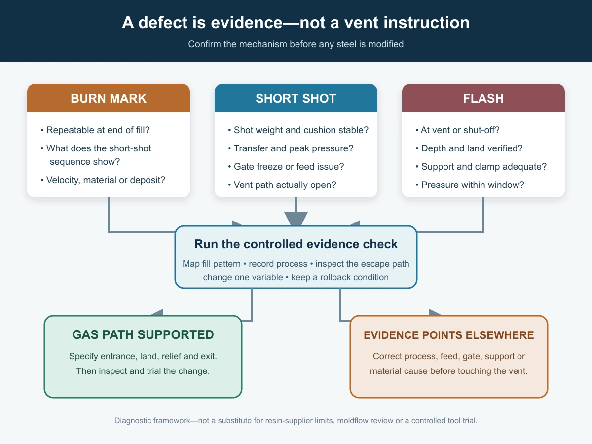
Do not diagnose venting from one symptom
Compressed gas can contribute to burns, incomplete fill, weak weld regions and surface blemishes. But the same observations can also come from an unstable shot, restricted gate, low material temperature, moisture, contamination, premature freeze-off or a leaking non-return valve. Flash near a parting line may indicate an over-deep vent, damaged shut-off, insufficient support, low clamp force or pressure that is simply too high.
DME’s troubleshooting guidance lists several checks for short shots and excessive flash, not a single automatic remedy. It notes that vents may clog, be crushed smaller under clamp load or be ground too deep for a particular material. That is why “open the vent” should be treated as a hypothesis, not a diagnosis. See the DME injection-molding troubleshooting guide.
| Observation | Evidence to collect before cutting steel | Competing explanations to test |
|---|---|---|
| Burn at a repeatable end-of-fill location | Short-shot sequence, fill-time result, injection-speed profile and vent condition | Trapped gas, excessive local velocity, contamination or thermal degradation |
| Intermittent short shot | Shot weight, cushion, transfer position, peak pressure and material condition | Venting restriction, feed inconsistency, check-valve leakage or premature freeze-off |
| Flash at a vent | Flash location, vent depth and land, shut-off contact, clamp force and cavity pressure | Vent too deep, damaged seal, insert movement or excessive pressure |
| Deposit building at the flow end | Resin/grade, additive package, cleaning interval and deposit location | Volatiles, trapped gas, contamination or unsuitable cleaning practice |
| Weak or visible weld line | Flow-front meeting location, temperature, pressure and vent access | Gas entrapment, low front temperature, unbalanced filling or gate position |
Find the real last-to-fill and air-trap locations
Air traps form where a flow front closes against a cavity wall or where converging fronts surround gas. Autodesk explains that hesitation, racetrack effects and unbalanced paths can move the trap away from the point farthest from the gate. Its Moldflow guidance recommends balancing flow and placing air traps where they can be vented, rather than assuming distance alone determines the location. See Autodesk’s air-trap troubleshooting guidance.
Use simulation as a prediction, then compare it with the real tool. A staged short-shot study can reveal how fronts advance and where they meet. Keep the resin grade, drying, melt and mold temperatures, screw recovery, transfer logic and injection profile controlled. Photograph each stage from the same orientation and record shot weight. Never create a short-shot series without a trial plan that protects the tool and machine.
Autodesk also warns that opposite speed changes can be appropriate for different mechanisms: a speed increase may reduce hesitation, while a decrease may reduce a burn associated with poor venting. The useful output is therefore not “faster” or “slower”; it is a documented relationship between the fill pattern, pressure, defect and available gas path. Review the Autodesk Air traps result scope before using it as evidence.
Specify four parts of a vent—not depth alone
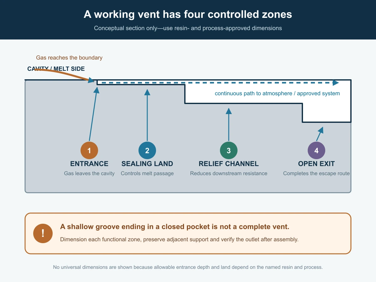
A useful vent detail separates four functions:
- Entrance: the location where gas leaves the cavity.
- Sealing land: the controlled shallow region that resists melt passage.
- Relief channel: the larger downstream passage that reduces flow resistance.
- Exit: the continuous route to atmosphere, a manifold or an approved vacuum system.
If the relief channel ends in a closed pocket, the drawing describes a groove—not a working vent. If the land is not dimensioned, a supplier cannot know where the flash-control region ends. If depth is specified without a resin and process basis, the value may be unsuitable even when the machining report is perfect.
Why one “standard depth” is unsafe
Material suppliers publish different starting points for different polymers. Celanese’s Celcon acetal guide, for example, gives a maximum vent depth and a downstream deepening arrangement for that material family. Its EVA guide uses a shallower entrance recommendation. Covestro’s mold-design guide distinguishes typical ranges for amorphous and semi-crystalline materials and states that resin and processing conditions determine maximum depth. Compare the Celanese Celcon processing guide, Celanese EVA molding guide and Covestro mold-design guidance.
Those numbers are source-specific examples, not a combined design table. The drawing should cite the approved resin supplier recommendation or a validated company standard, including revision. For a new resin grade, obtain written technical guidance instead of choosing the largest published value.
Select a vent route that reaches atmosphere
Parting-line vents are easy to inspect when the trap reaches the split. Deep ribs, bosses and enclosed ends may need another route. Options can include insert split lines, ejector pins or sleeves with controlled flats, replaceable vent inserts, porous media or vacuum-assisted systems. Each option changes manufacture, cleaning and validation.
DME describes short-shot studies and flow simulation as ways to identify critical locations, and lists parting-line, ejector-pin, porous and vacuum solutions. It also notes that porous vents can clog and require cleaning or replacement. Treat this as a menu of technologies, not evidence that a branded solution fits every resin or geometry. See DME venting solutions.
When a pin or sleeve becomes the gas path, the clearance or flat must be compatible with guiding, wear, ejection and flash control. Link the detail to the actual core pin or ejector-sleeve component; do not leave the mold-assembly drawing and pin drawing contradictory.
Protect insert support, sealing and serviceability
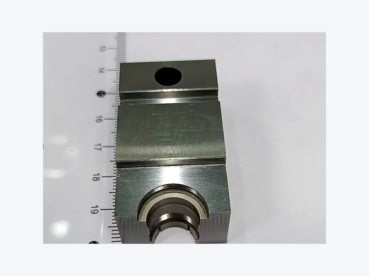
A vent cut into an insert changes more than airflow. It removes contact area, creates an edge that can wear or chip and may connect a cosmetic cavity surface to a parting line. Review:
- remaining bearing and shut-off area under clamp load;
- distance from thin edges, cooling passages, fasteners and high-stress corners;
- how the insert is oriented so a cleaned component cannot be assembled backwards;
- whether lapping, polishing or recoating would change the vent entrance;
- access for measurement, cleaning and future restoration;
- the escape route after the vent crosses the insert pocket.
For precision mold inserts, put vent surfaces and pocket interfaces in one datum strategy. A depth measured from a worn or polished cavity surface is not equivalent to the same number measured from a stable manufacturing datum.
Inspect what the drawing actually controls
Acceptance should establish that the vent is open, correctly located and dimensionally compatible with the seal—not just that “a vent was added.” Request:
- entrance depth at named locations and the measurement method;
- land length and width, including permitted transition radii;
- relief-channel depth/width and continuous outlet;
- burr, rolled-edge and damage criteria at the cavity boundary;
- contact evidence on adjacent shut-off surfaces where relevant;
- before/after photographs using a controlled orientation;
- the final insert and assembly revision.
Very shallow features may be close to the capability limit of common shop instruments. Agree whether a stylus instrument, optical profile, replica, calibrated comparator or another method is appropriate, and state where the trace or section is taken. Do not report more decimal places than the measurement system supports.
Validate the change with a controlled trial
Define success before the first shot. A practical trial compares the approved baseline and modified condition using the same material lot where possible, matched drying and temperature conditions, the same process window and a recorded fill sequence.
Track at least:
- defect location and severity at the same inspection lighting;
- fill time, transfer position, peak injection pressure, cushion and shot weight;
- the minimum condition that fills the part without the target defect;
- flash at the vent, parting line, pins and insert boundaries;
- weld-line appearance or functional test where relevant;
- vent condition after a defined number of cycles.
Release only if the target improves without creating unacceptable flash or another defect. A successful first shot does not establish a maintenance interval; keep the trial running long enough to observe deposit formation appropriate to the project.
Keep the vent effective in production
Vents are maintenance features. Record the clean condition, cleaning method, permitted tools and rejection limit. Scraping a shallow land with an uncontrolled abrasive can change the geometry; forcing debris down a porous path can make blockage worse. DME’s sintered-vent FAQ advises matching the cleaning agent to the resin and references ultrasonic cleaning for those products. See the DME sintered-vent FAQ.
Use production evidence to set the interval: cycle count or time at which pressure trend, deposit, burn or fill behavior changes. After repair, polishing or insert replacement, reverify both the vent and the adjacent sealing surface.
RFQ checklist and drawing-note template
Include these items in the quotation package:
- part, mold, insert and resin-grade revisions;
- gate location, predicted/observed last-to-fill and weld-line locations;
- symptom photographs, short-shot sequence and relevant process data;
- vent type and controlled entrance, land, relief and exit zones;
- resin-specific dimensional source and revision;
- datums, measurement method, report locations and burr criteria;
- insert support, sealing-contact and assembly requirements;
- cleaning access, replaceability and maintenance expectations;
- trial conditions, success criteria and rollback plan.
Template—replace every bracketed item:
Provide vent [ID] at zone [drawing reference] for resin [manufacturer, grade]. Control entrance depth [limit], land length [limit], width [limit] and relief channel [dimensions] to open exit [location]. Values are based on [approved source/revision]. Protect adjacent shut-off [ID]; no burr or rolled edge is permitted at the cavity boundary. Verify by [method] at [locations] and supply [report/photos]. Trial acceptance requires [defined defect result] with no flash above [approved criterion] within [process window]. No vent enlargement without written approval.
Frequently asked questions
Do burn marks always mean poor mold venting?
No. Trapped gas is one possible cause, but excessive velocity, contamination and material degradation can produce similar observations. Confirm the fill pattern and process evidence before modifying steel.
Where should a mold vent be located?
At a verified gas-trap or last-to-fill location with a continuous path to an approved exit. Simulation can predict locations; a controlled short-shot study helps confirm the real tool.
Can I use one vent depth for every plastic?
No. Published recommendations vary by material family and grade. Use the named resin supplier’s guidance or validated project standard, and include processing conditions and flash acceptance.
Is a deeper vent always more effective?
No. Depth may reduce flow resistance, but an excessive entrance can permit flash. More width, additional locations, a shorter land, a clearer relief path or a different vent route may be the better controlled change.
Can ejector pins vent a deep rib?
They can provide a route in some designs, but the flat or clearance must be coordinated with pin guidance, wear, ejection, cleaning and resin-specific flash control.
What should be inspected after adding a vent?
Inspect entrance depth, land geometry, relief and exit continuity, boundary condition, adjacent sealing contact and assembly orientation. Then validate the part and process in a controlled trial.
Source and scope note: Eight contextual external links lead to original manufacturer or software-provider guidance. Their dimensions and products are source-specific, not Huicheng performance guarantees. The diagnosis map, release logic and RFQ template are original editorial tools and do not replace resin-supplier approval or a mold trial.