A cooling hole is not a cooling system. A mold can contain accurately drilled waterlines and still produce a hot insert, unstable cycle time, leakage or part warpage. The real system includes the heat load, channel path, coolant supply, seals, plugs, fittings, flow resistance and the evidence used to release the tool.
For a precision insert, the difficult decision is not simply “How close can the waterline be?” It is: how can heat be removed evenly while the insert remains strong, sealed, manufacturable, inspectable and replaceable? This guide turns that question into a drawing, inspection and trial workflow that a mold buyer and component supplier can review together.
Define the thermal objective and complete supply-to-return circuit before placing a hole. Check the channel against cavity steel, fasteners, ejectors, shut-offs and removable-insert interfaces. Specify every seal and plug, verify continuity and leakage before molding, then release the design only when flow, temperature and molded-part evidence agree.
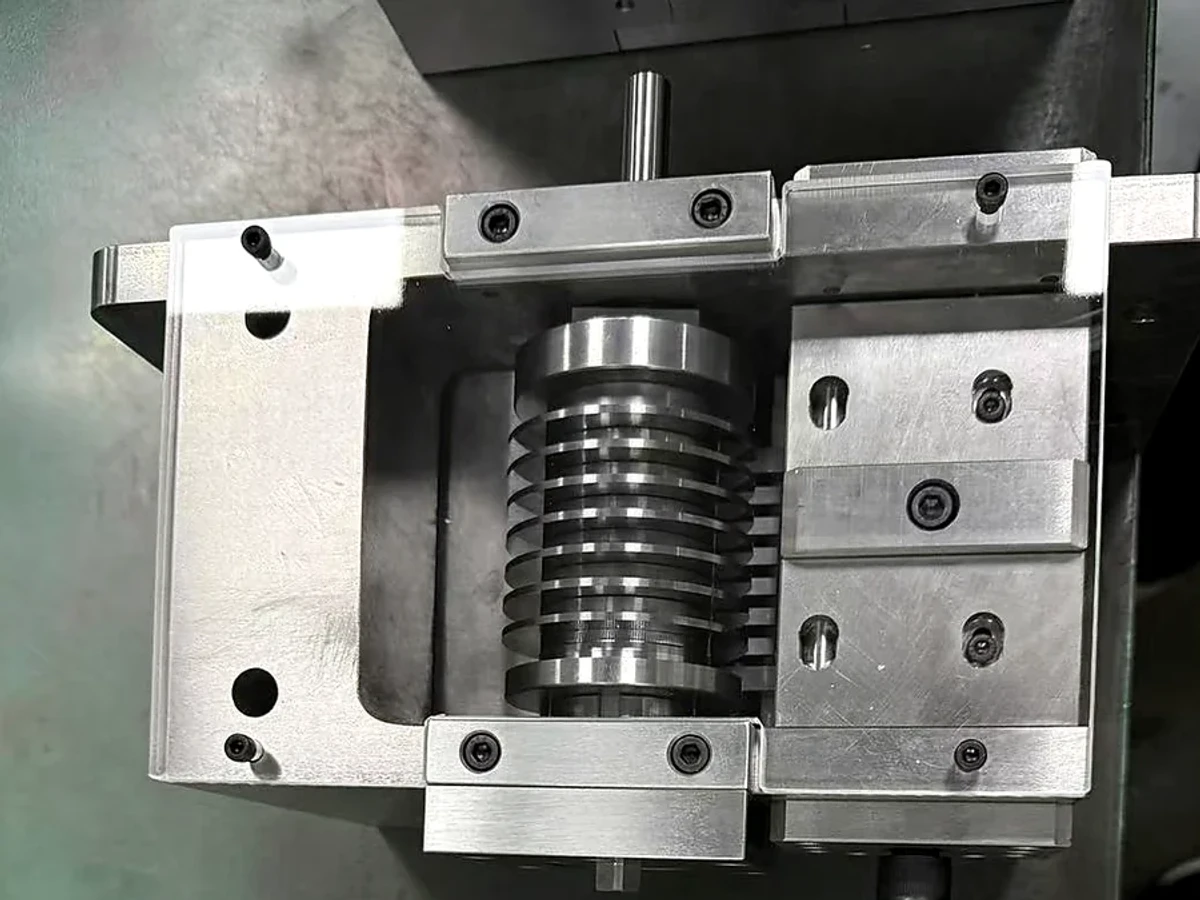
Start with the thermal symptom—not a hole pattern
Long cooling time, warpage, difficult ejection, dimensional drift and a hot region on the part can all justify a cooling investigation. None proves that one channel must be moved closer. Packing, gate freeze, wall thickness, resin condition, ejection timing, insert contact and measurement timing can produce similar observations.
Autodesk describes its Cooling Quality result as a way to identify where part shape and thickness tend to retain heat before detailed circuit assumptions are added. It separates temperature variance from cooling-time variance and warns that low-quality zones can have different causes. Use that logic to define the question before prescribing the hardware. See the Autodesk Cooling Quality result guidance.
| Observation | Evidence to collect first | Competing explanations to test |
|---|---|---|
| One repeatable hot region | Part thickness map, fill/pack result, circuit routing, local steel and stabilized surface-temperature map | Low local heat removal, thick section, poor insert contact or an inactive channel |
| Warpage changes after ejection | Part orientation, measurement time, cavity/core temperatures, packing history and ejection temperature | Uneven cooling, asymmetric packing, residual stress or early ejection |
| Cycle time gradually increases | Flow, supply/return temperature, pressure difference and maintenance history | Scale, blocked passage, pump change, hose restriction or hotter process conditions |
| Water appears near an insert | Leak location, seal condition, groove dimensions, assembly orientation and test pressure | Damaged seal, scratched face, wrong compression, cracked steel or a leaking plug |
| Two nominally identical cavities differ | Per-circuit flow and temperature, manifold connections, cavity dimensions and shot sequence | Unbalanced circuits, different heat load, restriction, packing or venting differences |
Draw the complete circuit from supply to return
A supplier cannot verify a line floating inside a CAD model. Give each circuit an ID and show its inlet, outlet, intended flow direction, drilled intersections, plugs, baffles or bubblers, insert crossings and connection sizes. Where circuits share a manifold, identify the branch arrangement and how each branch will be checked.
Covestro’s mold-temperature-control paper argues that channel position should be considered during the basic mold concept, especially for precision parts, rather than placed only after feed, motion and ejection features occupy the available space. The paper also describes the compromise between thermally favorable geometry and the rigidity needed to resist molding loads. Review the Covestro optimized mold temperature control paper for its stated scope.
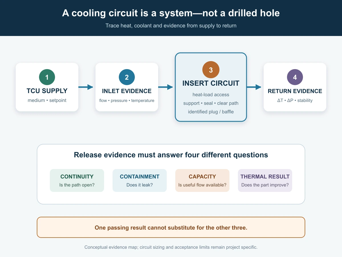
The circuit drawing should answer four practical questions:
- Continuity: can coolant travel from the named supply to the named return with no unintended blind pocket?
- Heat access: does an active passage serve each important heat-load zone?
- Hydraulic feasibility: can the available temperature-control unit overcome the complete circuit resistance at the required flow?
- Service access: can the circuit be connected, flushed, tested and cleaned after the mold is assembled?
Balance heat removal, uniformity and remaining steel
Moving a channel closer can increase local heat-removal potential, but it may also produce a stronger temperature wave at the cavity surface, weaken the insert or intersect another feature. Autodesk explains that smaller cavity-to-channel spacing can shorten cooling while increasing surface-temperature variation. Its general 2–2.5 channel-diameter spacing statement is a software design guideline—not permission to apply the same ratio to every steel, pressure, geometry or failure mode. Read the Autodesk cavity-to-channel distance guidance in context.
Cooling efficiency is not controlled by distance alone. Autodesk identifies channel distance, circuit Reynolds number and the temperature difference between coolant and circuit metal as interacting inputs, and notes that their combined relationship is nonlinear. The Autodesk circuit heat-removal efficiency result is useful for comparing sections inside one modeled system; it is not a stand-alone acceptance certificate.
Before releasing a channel near a precision mold insert, check:
- minimum remaining steel to the cavity, shut-off, fitting face and pocket boundary;
- distance to bolts, dowels, ejectors, slides, vents, sensor holes and EDM features;
- local pressure load and the consequence of a breakthrough or crack;
- heat-treatment, distortion and finishing sequence after deep drilling;
- whether repair, polishing or replacement would open the circuit or alter a seal face;
- tool access for drilling, plugging, cleaning and inspection.
Seal every transition at a removable insert
A waterline that crosses from a plate into a removable insert creates a functional interface. The seal depends on groove geometry, seal material, surface condition, assembly compression, pressure direction and temperature. The drawing must identify the approved seal and groove, not merely show a circle around the port.
Meusburger describes mold O-rings as primarily static seals at cooling-hole transitions and gives its own recommendations for axial/radial installation, groove filling and compression. Those values belong to the stated seal system. Use the actual seal manufacturer’s data for the selected size, material, medium and temperature rather than copying a percentage from a general article. See Meusburger’s mold O-ring design guidance.
Control the land around the port so the O-ring is supported after assembly. Protect the face from EDM recast, grinding pullout, burrs and scratches that cross the sealing path. If two identical inserts can be installed in opposite orientations, add a positive orientation feature or an unmistakable circuit identifier; a correct insert installed backwards can still block the flow path.
Choose a serviceable cooling architecture
Straight drilled passages are simple to inspect and clean, but may miss a deep core or follow an inefficient detour. Baffles and bubblers redirect flow into confined regions, but add orientation, assembly and maintenance conditions. Spiral or conformal passages can follow the heat load more closely, while increasing manufacturing, powder-removal, inspection and repair requirements.
Choose architecture by evidence, not novelty. For each alternative, compare:
- predicted temperature uniformity and required flow;
- pressure loss through the complete circuit, hoses and fittings;
- remaining structural support and risk of leakage into the cavity or pocket;
- how hidden passages will be cleaned and verified;
- replaceability of inserts, baffles, seals and plugs;
- what happens when scale or debris reduces the effective section.
A circuit that performs well only when perfectly clean may not be the lowest-risk production choice. A replaceable cooling insert may be preferable to an inaccessible passage if maintenance access is a project priority.
Inspect features a CMM cannot see by itself
A dimensional report can verify port positions, seal faces and accessible hole locations. It cannot establish that a hidden cross-drill is clear, a plug diverts flow correctly or a deep passage contains no chips. Combine dimensional, visual and functional evidence.
| Release question | Evidence | What it does not prove |
|---|---|---|
| Are ports and grooves in the right place? | Drawing-linked dimensional report from stable datums | Internal continuity or sealing under pressure |
| Is the hidden route connected correctly? | Borescope where accessible, circuit map, controlled air/flow check and plug record | Thermal performance in a molding cycle |
| Is the circuit leak-free? | Defined leak test with medium, pressure, duration and acceptance recorded | Required production flow or temperature uniformity |
| Does each branch receive useful flow? | Per-circuit flow and pressure evidence with the intended connections | Correct heat removal at the cavity surface |
| Does the molded part meet the objective? | Stabilized trial data and part inspection at a defined time | Long-term cleanliness or maintenance interval |
At manufacture, document drill entry/exit, intersection depth, plug type and final cleaning. Deburr any point where a seal, baffle or bubbler passes. Protect ports from blasting media and polishing compound. If a channel is produced additively, define powder-removal and internal-surface evidence appropriate to the process.
Bench-test leakage, blockage and flow
Test before the mold reaches the press. Define the safe test medium, pressure, duration, connection state and acceptance limit for the actual mold and components. A universal pressure value is unsafe because plugs, seals, hoses, plates and inserts may have different ratings. Air testing also stores compressible energy; use an approved guarded procedure.
DME describes pressure, blockage and leak testing as distinct cooling-channel checks in its CoolingCare process. That distinction is useful even if another test system is used: a circuit can be leak-free yet restricted, or open yet routed incorrectly. See the DME scientific mold cooling overview.
Record each circuit separately. A useful bench report includes circuit ID, connection drawing, test medium and temperature, supply/return pressure, flow, hold time, visible leakage, cross-circuit communication and pass/fail disposition. If multiple circuits are tested together, a good total flow can hide one blocked branch.
Validate thermal performance in a controlled trial
After bench release, validate the cooling objective under molding conditions. Hold resin, drying, melt temperature, fill/pack sequence, coolant supply and measurement method stable. Allow the mold to reach a defined repeating condition before comparing temperatures or parts.
DME’s FloSense material treats flow, inlet/return temperature and pressure difference as complementary signals and notes that changes can indicate restrictions, leaks, scale or equipment issues. Use that principle without assuming its product is required. A low temperature difference alone is not automatically good: it must be interpreted with flow, heat load and part results. See DME FloSense process guidance.
Autodesk describes cooling design as a compromise between temperature uniformity and cycle time and lists software criteria for circuit and mold results. Those numbers are analysis guidelines tied to defined assumptions, not universal shop acceptance limits. The project team should approve its own part temperature, warpage, cycle and stability criteria using the selected resin and equipment. Review Autodesk’s criteria for assessing cooling performance.
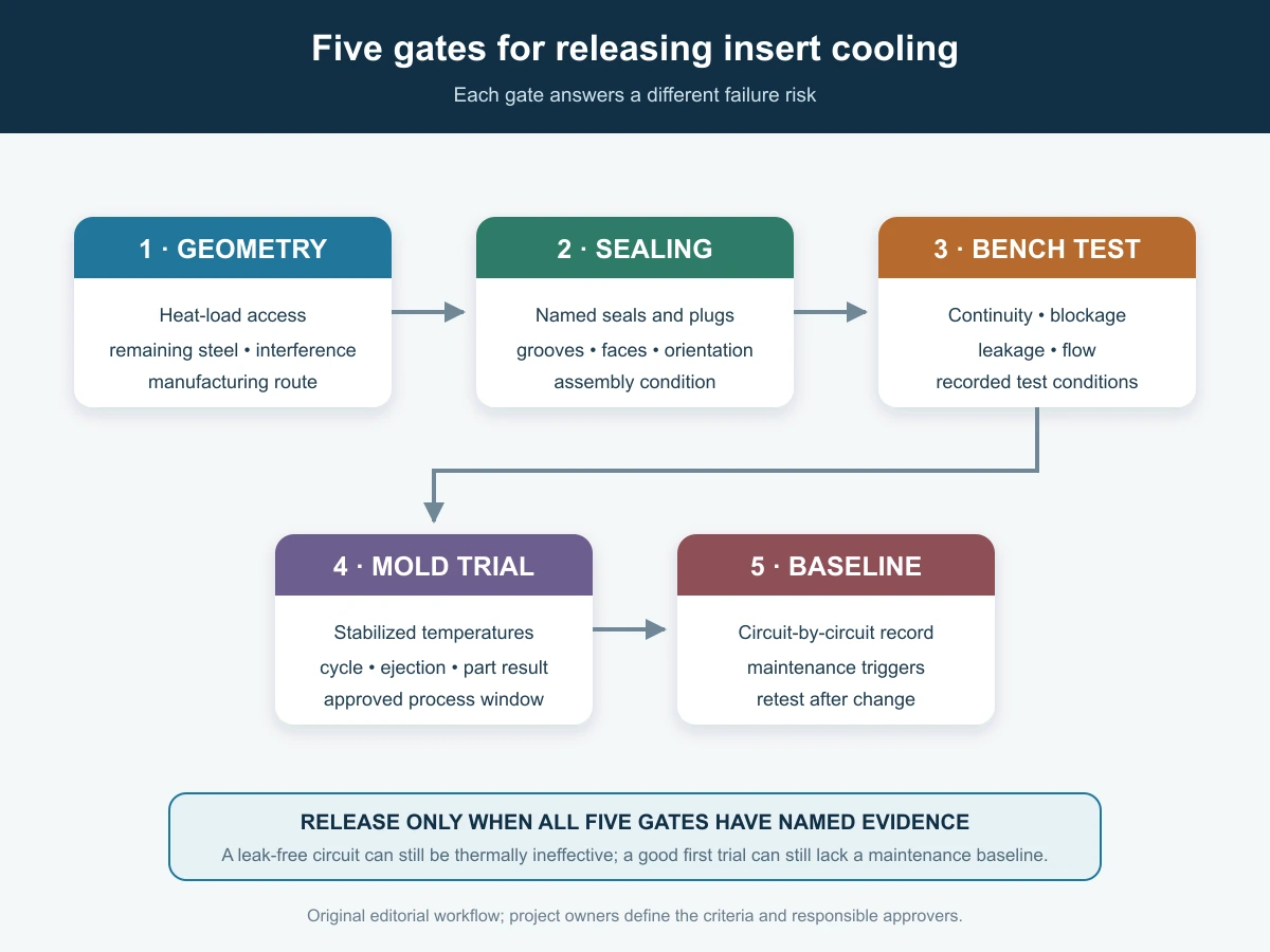
For a controlled mold trial and injection-molding validation, record at least:
- temperature-control unit, coolant, supply temperature and stabilized flow per circuit;
- inlet/return temperature and pressure at named measurement points;
- cavity/core or insert surface-temperature method, location and timing in the cycle;
- cycle time, cooling time, ejection condition and interruptions;
- part dimensions at a defined time after molding, warpage orientation and inspection method;
- leakage, condensation, hose movement and seal condition after the run.
Infrared readings depend on surface condition, viewing angle and emissivity; shiny tool steel can mislead. If thermal imaging is used, define the measurement surface and method. Compare the same locations under the same conditions, and use contact or embedded sensing where the required decision cannot be supported by an uncontrolled image.
Preserve the circuit in production
Cooling performance can drift even when the steel drawing does not change. Scale, corrosion products, hose debris, a damaged O-ring, a shifted baffle or a different temperature-control unit can change the hydraulic system. Baseline records make that drift visible.
Set cleaning and inspection intervals from production evidence rather than habit. Track per-circuit flow, temperature difference, pressure difference, cycle time and relevant part dimensions. Define permitted cleaning chemistry and neutralization for the steel, seals and plugs. After repair or insert replacement, repeat the tests affected by the change instead of relying on the original mold report.
RFQ checklist, drawing note and FAQs
Cooling-system RFQ checklist
- part, mold, insert and resin revisions with the thermal objective;
- heat-load or cooling-analysis files, assumptions and named result views;
- circuit IDs, inlets, returns, flow direction and connection sizes;
- channel geometry, intersections, baffles, bubblers, plugs and insert transitions;
- minimum remaining-steel and interference checks;
- seal manufacturer, part number, material, groove detail and approved medium/temperature;
- dimensional, continuity, cleaning, leak, blockage and flow evidence;
- trial setup, stabilization rule, measurement locations and part acceptance criteria;
- maintenance access, spare seals/components and retest requirements.
Drawing-note template—replace every bracketed field:
Cooling circuit [ID] shall run from port [inlet] to [return] through features [references] in the indicated direction. Install [approved plug/baffle/seal IDs] per supplier-controlled details. Protect minimum remaining steel [drawing requirement] and sealing surfaces [IDs]. After final cleaning and assembly, verify dimensional locations [report], continuity [method], leakage [medium/pressure/duration/limit] and flow [conditions/limit]. Trial release requires [stabilization rule], [temperature evidence], [cycle condition] and [part criteria]. No rerouting, plug substitution or seal-groove change without written approval.
Does a closer waterline always cool better?
It can increase local heat removal, but it may worsen cavity-surface temperature variation or reduce structural margin. Evaluate distance with channel size, spacing, flow, steel, heat load and part-quality requirements.
Can one flow reading prove every parallel circuit is open?
No. A total value can hide an underperforming branch. Measure or balance critical branches individually and keep the manifold arrangement in the test record.
Is a leak test enough to release an insert cooling circuit?
No. It addresses containment under the stated conditions. Continuity, flow, thermal response, part quality and maintenance access require separate evidence.
Should every removable insert contain cooling?
No. The heat load, available steel, seal risk, component size and replacement plan may favor cooling in the surrounding plate or another architecture. Compare alternatives at the mold-concept stage.
Can a CMM inspect an internal waterline?
It can locate accessible openings and related datums, but cannot by itself prove hidden continuity, cleanliness or correct plugs. Combine dimensional and functional tests.
What data should accompany a replacement cooled insert?
Supply the matched circuit revision, port and seal geometry, plug/baffle configuration, pressure/flow test conditions and the baseline trial evidence. A replacement that fits mechanically can still fail hydraulically.
Source and scope note: Eight contextual links lead to original software-provider, material-producer or mold-component supplier guidance. Their guidelines and products remain source-specific and are not Huicheng performance guarantees. The circuit map, release gates, tables and RFQ template are original editorial tools; they do not replace a structural calculation, resin approval, guarded pressure-test procedure or controlled mold trial.