The correct wire EDM internal corner radius is the one that satisfies the component’s function and can be manufactured and verified—not simply the smallest radius a machine can advertise. For a mating insert or die opening, the important question is whether the complete permitted profiles can assemble without interference. For a forming or cutting feature, the corner may instead define the product itself.
A drawing that shows a sharp CAD corner and adds “wire EDM” leaves a consequential decision unresolved. The supplier must either interpret the corner, request a change or choose a more demanding process. Settle that decision before comparing quotations, especially when the part must fit an existing component.
A maximum internal radius, a minimum strength-related radius and a permitted corner relief are three different requirements. Treating them as interchangeable can produce a part that passes one dimension but fails its intended function.
Why does wire EDM leave a finite internal corner radius?
Wire EDM removes conductive material around a traveling wire electrode, with a discharge gap between the wire and the workpiece. Sodick describes the wire passing through the workpiece between upper and lower guides, with guide movement also enabling tapered profiles.[1] The wire is not a zero-width line, so a square change of direction in the CAD outline does not create a mathematically sharp internal corner.
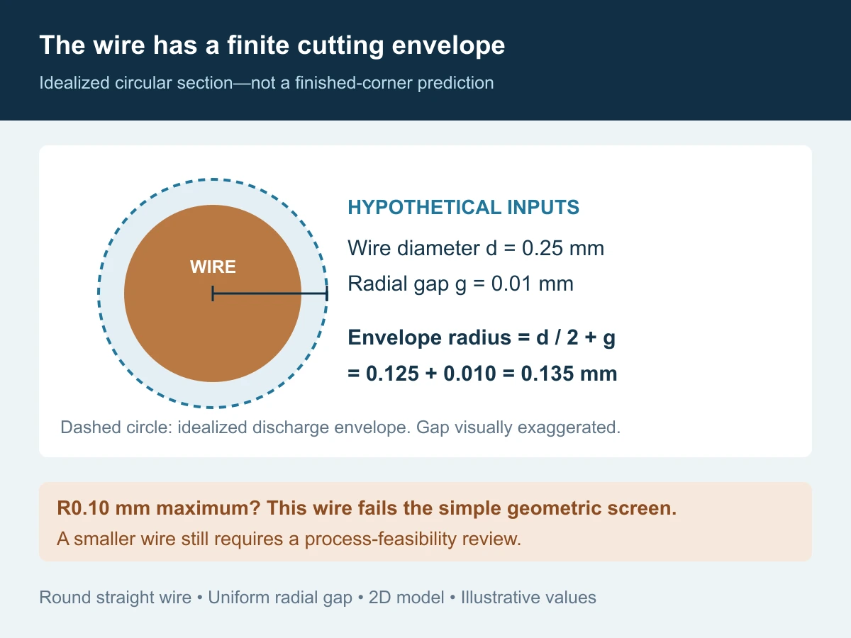
For an idealized straight-wire, two-dimensional cut with a uniform radial discharge gap, the effective circular cutting envelope has radius re = dw/2 + g, where dw is wire diameter and g is the assumed radial gap. This is a geometric screening model for a 90-degree internal corner, not a formula predicting the finished radius or a machine compensation setting.
Consider hypothetical values of dw = 0.25 mm and g = 0.01 mm. The idealized envelope radius is 0.135 mm. That combination cannot produce an unrelieved R0.10 mm maximum internal corner within this model. Even the bare wire radius, 0.125 mm, exceeds the proposed limit. All values are illustrative; the gap is not a recommended machining parameter.
The reverse conclusion does not follow: choosing a wire small enough to pass this geometric screen does not prove the required corner can be delivered. Actual corner form also depends on the process conditions and wire behavior. Do not apply this internal-corner screening rule unchanged to an external convex corner, where the wire travels around the outside of the retained material.
First decide what the corner is allowed to do
Before asking for a smaller radius, classify the feature. A non-contact clearance corner has different constraints from a sealing boundary, a loaded support or a cutting profile. Mark those functions on the controlled drawing or an accompanying approved review sketch.
| Corner function | What needs definition | Risk of an informal change |
|---|---|---|
| Mating or locating opening | Permitted profile, mating part and assembly clearance | Material remaining in the corner blocks full seating |
| Forming, cutting or sealing boundary | Required functional contour and any prohibited relief zone | A relief changes the product contour or interrupts the intended boundary |
| Loaded internal transition | Designer-approved radius range, section and load requirements | “As sharp as possible” conflicts with the strength-related design intent |
| Non-contact clearance region | Permitted material-removal envelope and remaining section | Uncontrolled relief removes needed support or reaches an adjacent feature |
Be precise about the direction of the limit. A maximum internal radius may be used to restrict how much material occupies a mating corner. A minimum radius may be required by the design to avoid an excessively sharp internal transition. If both requirements matter, the approved specification must resolve them together; the supplier should not choose which one to ignore.
Radius alone also does not establish a fit. Compare the mating contours in the same assembly reference, including their sizes, positions, orientations and permitted variations. An internal fillet can obstruct a sharp external corner even when the straight walls have clearance. Conversely, two parts do not necessarily interfere merely because their stated corner radii differ.
Our recommendation is to review the permitted material envelopes: where may material remain on each component, and where must space be available? A nominal CAD overlay is useful for discussion, but the acceptance decision must address the allowed variation, not just the nominal shapes.
Fine wire, relief, a mating-part change—or another route?
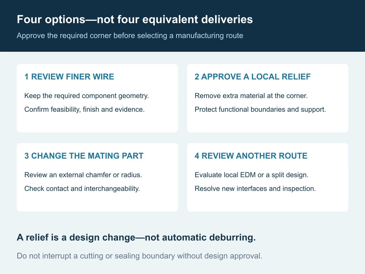
There are several ways to resolve a difficult corner. Each changes something different, so quotations should identify the proposed option rather than simply promising “sharp corners.”
1. Retain the design and review a finer-wire process
A finer wire can expand the range of small internal details that can be considered. It is not a free improvement: Mitsubishi Electric discusses thinner wire as one approach to smaller corners, with productivity implications, and describes machine-specific corner-control technology as another factor.[2] This supports a feasibility review, not a universal minimum radius or a claim that Huicheng operates the cited machine.
Ask whether the proposed wire, workpiece thickness, material, access and finishing strategy support the actual feature. Compare the quoted finished result and inspection scope. A wire diameter listed in a machine brochure is not evidence that every part geometry is achievable with it.
2. Add an approved local relief
A corner relief intentionally removes extra material beyond the otherwise required contour. It can give a mating corner space without requiring the entire opening to be cut with a smaller wire. But a “dog-bone” or other relief is a design change, not routine deburring.
Define its location, size and extent. Confirm that it does not interrupt a cutting or sealing boundary, remove essential bearing area, reduce a critical ligament or communicate with another feature. A relief that solves assembly interference may be unacceptable elsewhere in the same component.
3. Change the mating component’s corner
An approved chamfer or radius on the external mating corner may resolve the conflict. Check its effect on locating area, contact, strength and product geometry. Also establish whether the altered component must remain interchangeable with existing tooling; solving one pair is not automatically a solution for the spare-parts population.
4. Review another manufacturing or assembly approach
A local sinker-EDM operation or a split-component design may be worth evaluating where wire access or the required contour is unsuitable. Neither option automatically creates a zero-radius corner. Both introduce their own locating, finishing, assembly and inspection questions, which belong in the quotation.
A correct top outline does not prove the whole wall is correct
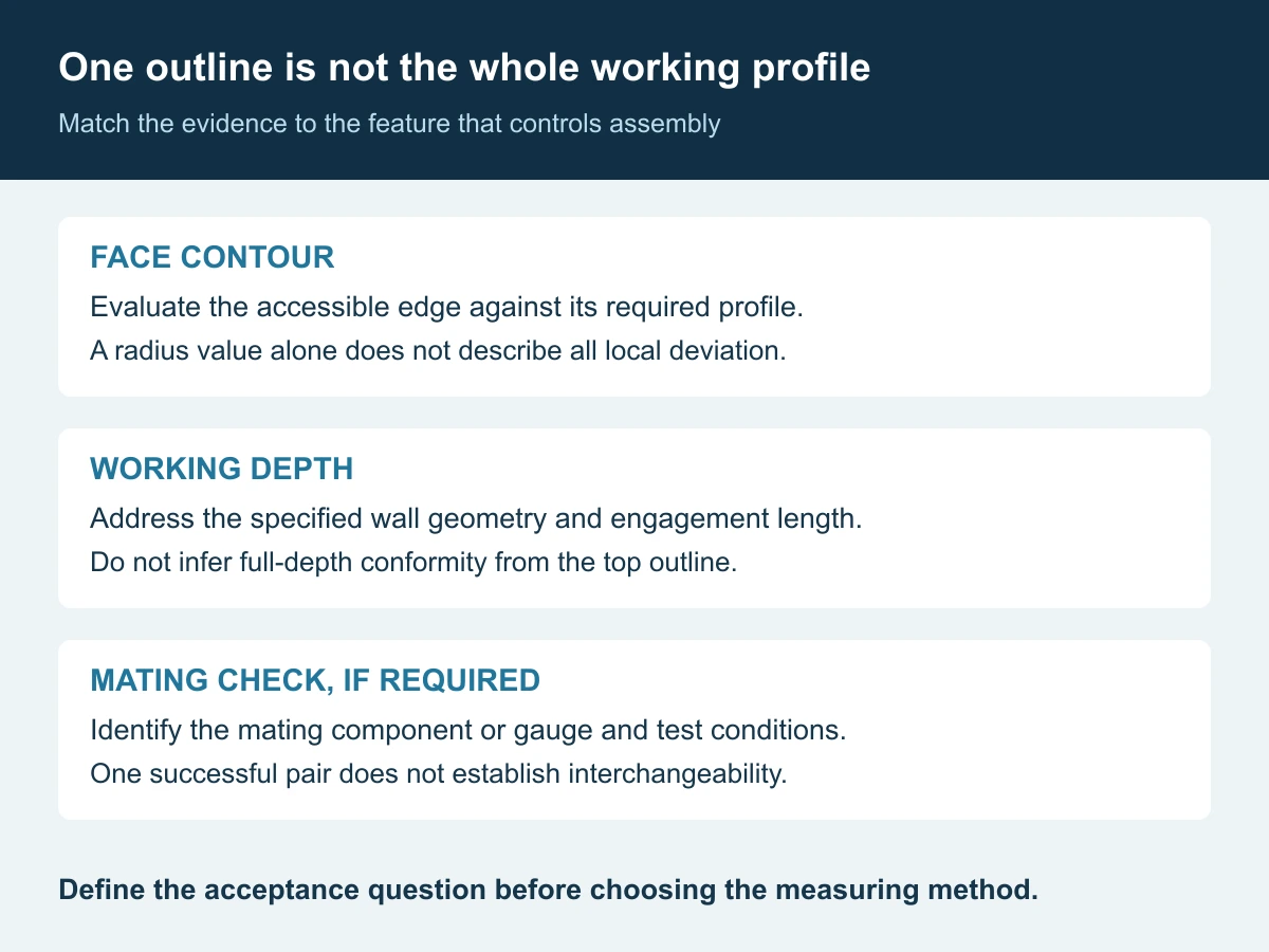
The corner exists through a working thickness, not only in the visible top face. Makino’s wire-EDM tutorial explains how wire behavior can leave excess material at an internal corner and how shape error within a thicker workpiece may not be represented by the condition near the guides.[3] These are process risks to address, not a claim that every wire-cut part has such errors.
For a mating through-profile, identify the working engagement length and whether the wall should be straight, tapered or relieved. Do not rely on a top-face radius reading to establish the full-depth relationship. A drawing with an intentional taper needs acceptance tied to the specified sections and reference geometry.
Likewise, a promise of “multiple skim cuts” describes a process, not an inspection result. The buyer needs the accepted profile in the final supplied condition. The supplier should select a suitable machining strategy; the purchase order should define what that strategy must achieve.
Confirm access before debating the smallest radius. An enclosed through-contour needs a way to thread the wire, typically a start hole, unless another approved entry arrangement is provided. The surrounding geometry must also permit the required wire and guide access. A blind pocket with an intact floor is not an ordinary through-wire-cut feature.
Identify any start hole, entry path or cut-off location that could affect a retained surface. Where later grinding, coating or polishing changes a functional profile, specify whether acceptance occurs before or after that operation. Do not quietly blend a nonconforming corner by hand and report the original drawing as satisfied.
Specify the inspection question before selecting the instrument
“CMM report included” is incomplete if the proposed probe cannot reach the critical transition. Renishaw identifies access to the feature and accuracy at the contact point as essential to successful measurement; stylus size, rigidity and configuration affect the result.[4] A small reported radius should be supported by a method suited to that geometry.
For each critical corner, agree the characteristic and the evidence:
- Local corner shape: identify the arc or transition to be evaluated, its permitted contour and how adjacent straight sections are treated in the evaluation.
- Relationship to the rest of the part: establish the specified datums and location/orientation requirements, not only a best-fit radius value.
- Through-thickness condition: define which sections or surfaces require evaluation and how inaccessible regions will be addressed.
- Measurement suitability: confirm access, resolution, uncertainty and the reporting method are appropriate for the requirement.
- Assembly evidence, if required: identify the mating component or gauge and the agreed test conditions.
An optical measurement of an accessible edge can support a two-dimensional contour check, but it does not automatically establish the shape of an inaccessible wall below it. A fitted circle reported as “R0.10” also does not, by itself, show whether local material lies outside the allowed profile. Ask for the deviation information relevant to the requirement.
A functional fit test can complement dimensional evidence. It should not silently replace drawing requirements: one part fitting one sample says less than a demonstrated interchangeability requirement across an approved set of mating limits.
What should a wire-EDM corner RFQ contain?
Send the component model and controlled drawing, plus the relevant mating geometry. Flag the corners that actually control function. It is more useful to identify two critical transitions than to apply an unexplained “all corners sharp” note to the whole part.
| RFQ input | Decision it enables |
|---|---|
| Feature ID, revision, material and supplied condition | Review the correct geometry and process route |
| Required profile, radius limits and datum references | Separate size, location, form and corner requirements |
| Working thickness, taper and wire access | Assess the whole cut rather than one drawing view |
| Mating component and functional contact areas | Check interference and protect locating or sealing regions |
| Permitted changes and prohibited relief zones | Quote alternatives without silently changing the design |
| Final surface state, quantity and inspection evidence | Compare complete accepted deliveries on the same basis |
For Huicheng’s EDM and wire EDM services, provide the available geometry and explain what the corner must do. Huicheng can manufacture to customer drawings and help customers prepare drawings. If the requirements are incomplete, agree the drawing-development scope and approve the resulting revision before manufacture.
Request a base quotation to the current approved design and clearly separated alternatives where useful. If feasibility requires a trial cut or a changed inspection method, state that development stage and its approval point. Do not compare a fixed finished-part quotation against an exploratory machining estimate as if the deliverables were identical.
The practical goal is not the sharpest possible corner. It is a controlled corner that preserves the intended function, has an agreed manufacturing route and can be accepted with meaningful evidence.
Frequently asked questions
Can wire EDM make a perfectly square internal corner?
Not a mathematically zero-radius corner using an ordinary round wire. Specify a finite acceptable profile, or review an approved relief or alternative design. A sharp-looking CAD intersection is not a complete physical requirement.
Is the minimum internal radius always half the wire diameter?
No. Half the diameter is only the bare wire radius. The discharge gap and actual machining behavior also matter. The idealized calculation above is a feasibility screen, not a guaranteed finished-radius rule.
Can I add corner relief after the supplier has quoted?
Only through an approved design change. Reconfirm the remaining section, functional boundaries, mating relationship, inspection scope and price or lead-time effects before cutting.
Is a smaller internal radius always better?
No. It may protect one mating condition while conflicting with a strength-related radius requirement or adding unnecessary manufacturing difficulty. The required function determines the acceptable shape.
References and scope notes
Manufacturer sources support the cited process and measurement principles, not Huicheng-specific machine performance or minimum-radius guarantees. The geometric example, decision tables and inspection framework are editorial analysis. All illustrations are original explanatory diagrams, not customer parts or machining records.
- Sodick Europe: Wire EDM Technology — traveling-wire arrangement, guide motion and discharge-gap context. ↩
- Mitsubishi Electric: MG Series EDM development, Part 2 — finer-wire and corner-control tradeoffs; machine-specific discussion. ↩
- Makino: EDM Wire Tutorial — wire behavior, corner error and through-thickness concerns; historical speeds and prices are not adopted here. ↩
- Renishaw: Precision styli for metrology — feature access and stylus selection for reliable contact measurement. ↩