A core pin that measures correctly on the inspection bench can still produce an off-center hole or uneven wall thickness during injection molding. Ordering the same geometry in a harder steel may leave that problem unchanged.
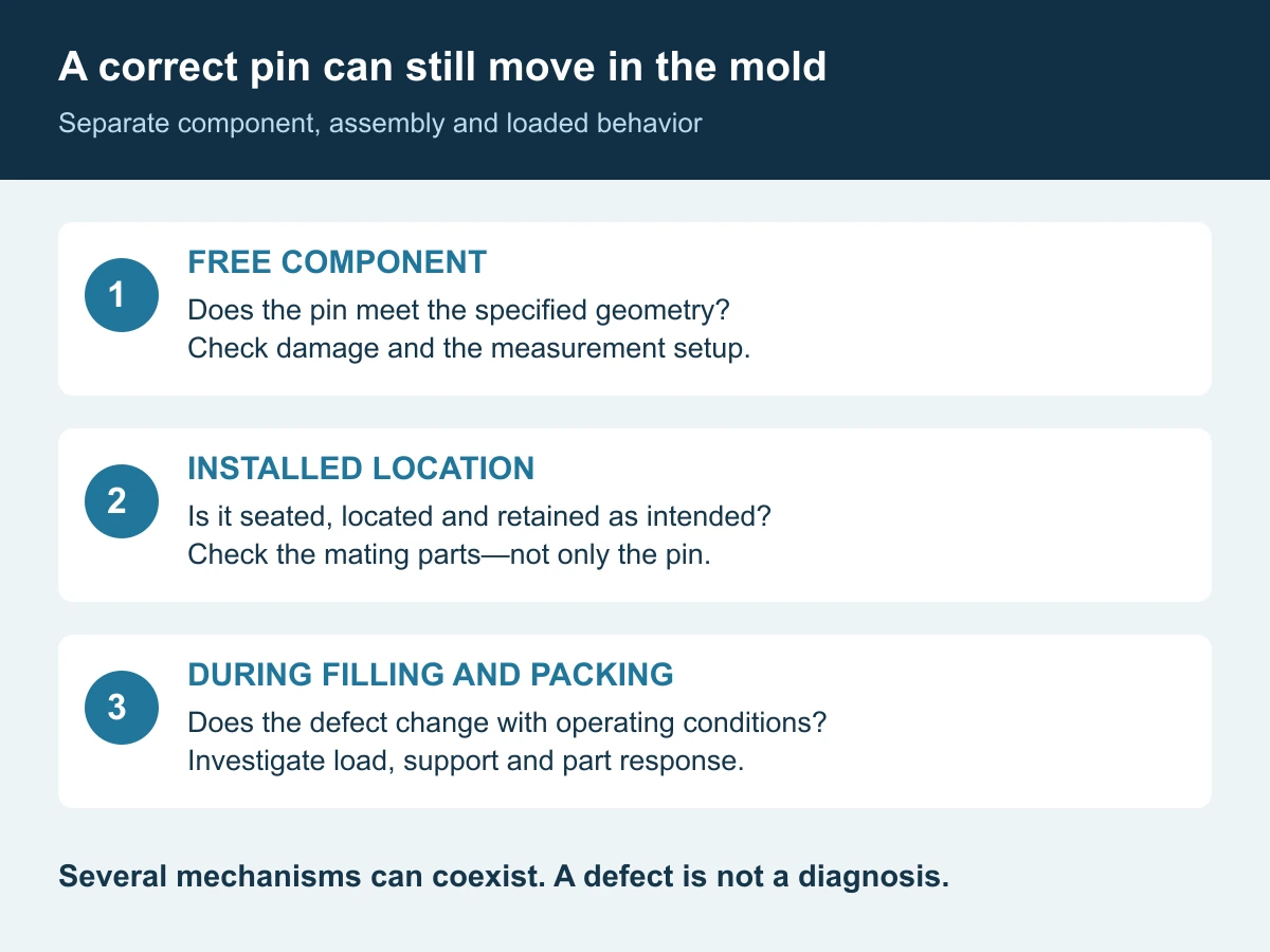
The purchasing decision should begin with a different question: is the pin wrong before installation, incorrectly located in the assembled mold, or moving under molding loads? Those conditions require different evidence—and often different corrective actions.
To address core pin deflection, first separate initial alignment error from movement during molding. Then review the unsupported span, actual support conditions, pin section and pressure imbalance. Hardness helps describe a material’s resistance to indentation; it is not the elastic modulus that governs bending stiffness. Agree the component dimensions, assembly checks and molded-part acceptance criteria before ordering a replacement.
1. Separate a bent pin, a misplaced pin and a pin that bends in service
Here, a core pin is a mold component that forms an internal feature in the plastic part. This guide concerns lateral bending during filling and packing, not the separate problem of an ejector pin buckling under an axial ejection load.
Autodesk identifies machining or setup misalignment, mold or platen deformation, and pressure differences across the core as distinct causes of core shift.[1] An off-center molded feature alone does not identify which mechanism is responsible.
| Observation | Evidence to collect | Purchasing implication |
|---|---|---|
| The uninstalled pin fails its specified geometry | Relevant diameters, straightness, tip position relative to locating features, and the inspection setup | A corrected component may be needed; distinguish manufacturing error from later damage |
| The pin conforms, but the assembled position is wrong | Seating, locating bore, retention, mating alignment and possible interference | Another conforming pin may reproduce the same offset |
| The defect changes with molding conditions | Cavity identity, defect direction, process records and corresponding part measurements | Investigate loaded movement and process sensitivity; do not assume the steel is defective |
| The pin remains bent after removal | Handling, collision and operating history, plus appropriate damage assessment | Investigate permanent deformation; a fresh pin does not remove the original overload |
These are starting points, not exclusive diagnoses. A slightly misaligned assembly can also deflect under load. Process-sensitive part measurements can involve shrinkage or warpage rather than pin movement alone.
Useful first step: map the error by cavity and by position along the molded feature, using a consistent measurement method. Preserve the pin’s orientation and assembly identity. A single averaged wall-thickness number can conceal the directional pattern needed for diagnosis.
2. Why harder steel does not automatically mean less deflection
Three properties answer different questions:
- Elastic modulus: how strongly the material resists elastic strain; together with geometry, it determines bending stiffness.
- Yield strength: the stress level associated with the onset of permanent deformation under the relevant conditions.
- Hardness: resistance to indentation, useful in specifying a material condition but not interchangeable with either property above.
For example, Uddeholm’s Orvar Supreme data sheet reports elastic modulus by temperature separately from strength values at different hardness levels.[2] A hardness value should not be substituted for modulus in a deflection calculation.
If two candidate steels have similar elastic modulus in service, changing between them may produce little change in elastic bending at the same geometry and load, even when their hardness differs. A material change can still matter for permanent set, wear, corrosion or fracture resistance. The point is to specify the property needed for the observed failure—not simply the highest available HRC.
Ask the designer to distinguish an elastic movement problem from a strength or damage problem. No single grade or hardness range is recommended here; selection depends on the pin’s geometry, temperature, resin, surface requirements and loading.
3. Unsupported length can matter more than a small material change
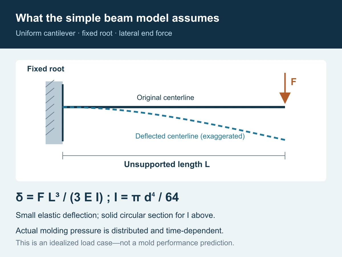
A simple beam calculation is useful for understanding sensitivity, provided its assumptions stay visible. For a straight, uniform cantilever with a lateral point load at its free end:
For a solid circular section: I = π d⁴ / 64
F = lateral end force; L = unsupported length; E = elastic modulus; I = second moment of area; d = diameter.
The cantilever relation appears in MIT’s solid-mechanics reference.[3] It assumes a fixed root, small elastic deflection and constant section. It is not a complete model of pressure acting on a stepped, supported or cooled core pin.
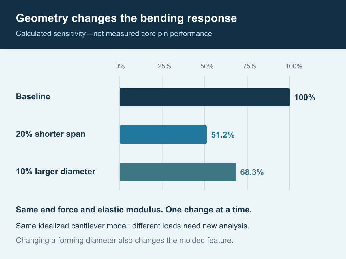
Calculated illustration—not production data: hold the same end force and modulus, and change one variable at a time. Relative to the original pin:
| Idealized change | Deflection ratio | Result |
|---|---|---|
| No change | 1.000 | 100% of baseline |
| Unsupported length reduced by 20% | 0.8³ = 0.512 | 51.2% of baseline |
| Diameter increased by 10% | 1 / 1.1⁴ ≈ 0.683 | 68.3% of baseline |
These ratios are an algebraic comparison, not predicted improvements in a particular mold. Increasing a forming diameter changes the molded feature. Altering the support can change both the load and the boundary conditions. Neither adjustment should be made without design approval.
Do not carry the length-cubed rule into every loading case: a uniformly distributed load has a different length dependence. Stepped sections, internal passages, contact and temperature-dependent properties also require a more representative analysis.
4. A nearby sleeve is not automatically an effective support
Mark the actual locating and supporting surfaces on an assembly section. Overall pin length is not necessarily the unsupported length. Conversely, a long portion surrounded by another component is not necessarily supported if the clearance, alignment or contact arrangement does not provide the assumed restraint.
For each proposed support, review:
- Where lateral load is transferred into the mold structure.
- Which directions are constrained, and whether rotation is restrained.
- Whether contact exists during the relevant part of the cycle.
- The mating clearances, alignment and thermal movement.
- The consequences for demolding, wear, maintenance and replacement.
Do not assume that components with the same nominal diameter are compatible. DME specifically cautions that its catalog core pins and ejector sleeves may require modification to work together because their tolerance ranges differ.[4] That is a product-specific warning, not a universal prohibition; it illustrates why the actual mating specifications matter.
An ejector sleeve can perform an ejection function, and a sleeve can serve a guiding role in a suitable design. Neither label establishes that it provides the restraint assumed in a bending calculation. Avoid prescribing an arbitrarily tight fit as a cure: movement, operating temperature and the intended assembly function still need to be accommodated.
5. Investigate pressure imbalance—not just the machine’s pressure setting
For lateral bending, the important question is the net loading across and along the core as the cavity fills and packs. A machine pressure setting alone does not specify that loading. Do not apply the displayed injection pressure to the pin’s entire projected area and treat the resulting force as a verified side load.
Ask the molding team to relate the defect pattern to gate and flow arrangement, resin condition, process history and any recent tooling changes. Where warranted, a controlled trial or a suitable flow-and-structural analysis can help distinguish alternatives. Blindly lowering pressure may create other part defects without resolving the cause.
Simulation is only as useful as its inputs and constraints. Autodesk’s troubleshooting guidance highlights geometry representation, correctly applied constraints and whether filling and packing are included.[5] A rigidly fixed support in a model should not be accepted without checking how the real pin is retained.
For a reviewable analysis, request the support assumptions, material properties, load history, displacement direction and timing—not only a colored maximum-displacement image. Identify which mold-system movements were excluded. Compare the prediction with relevant trial measurements before treating it as acceptance evidence.
6. Define acceptance at three levels
A supplier can verify the delivered component without proving that the complete mold will produce acceptable parts. Keep those responsibilities separate, then connect them in the project plan.
| Acceptance level | What to define | What it does not prove alone |
|---|---|---|
| Delivered pin | Specified geometry, material condition, finish, identification and inspection evidence | Correct seating or loaded performance in the mold |
| Assembled tooling | Location, seating, retention, intended contact and movement | Acceptable molded results across the agreed process conditions |
| Molded part | Feature location, wall thickness, appearance and function at agreed trial and measurement conditions | That every future process setting or tool-life condition will be acceptable |
For a slender pin, an inspection fixture must not unintentionally force the part straight and hide the characteristic being measured. Specify whether inspection is free-state or restrained, the locating references, and which characteristic is being evaluated. A runout reading should not be relabeled as straightness without considering what the setup actually measures.
Agree who checks the mold assembly, who runs the trial and who releases the molded part. This prevents a replacement order from ending in a dispute where “pin passed inspection” and “part still fails” are both true.
7. What to send Huicheng for a core pin inquiry
Huicheng manufactures custom core pins and related pin-and-sleeve components to controlled specifications. In addition to manufacturing from customer drawings, Huicheng can help customers prepare drawings. Where deflection is a concern, provide the surrounding assembly information rather than only the pin’s diameter and overall length.
- Geometry: drawing/model revision, forming profile, steps, head and locating features, with critical tolerances identified.
- Assembly: a section showing supports, retention, mating parts and any intended movement or contact.
- Operating context: resin designation, relevant temperatures, gate arrangement and available process or analysis records.
- Failure evidence: cavity identity, defect direction, measurements, photographs and whether the pin retains a bend after removal.
- Supply scope: material condition, finish, coating if applicable, quantity, identification and required inspection records.
- Approval: who approves drawing changes, verifies assembly and accepts trial parts, plus the required delivery date.
If no complete drawing exists, send the available sample, sketch and mating information. Identify unknown dimensions or operating conditions rather than guessing them. Drawing assistance needs an agreed scope and customer approval before manufacturing; it is not an automatic guarantee of the mold’s structural or processing performance. Confirm any simulation, on-site diagnosis or trial service separately.
The better buying question: “Can you supply this pin to the approved requirements, and what information is missing to define it correctly?” That is more useful than “Can you make the same pin harder?”
Buyer questions
Can a pin pass inspection and still cause uneven wall thickness?
Yes. Component geometry, installed alignment and movement under load are different conditions. Investigate all relevant stages; also consider molding shrinkage and warpage before attributing the final part error solely to the pin.
Is there a universal maximum length-to-diameter ratio?
No single ratio establishes suitability. Load distribution, support, section changes, temperature and allowable movement matter. Treat a supplier’s rule of thumb as a screening aid with stated assumptions, not a performance guarantee.
Should we increase the pin diameter?
Only if the design allows it. Increasing a solid circular section raises its bending stiffness, but a forming diameter also controls the plastic feature. Review support and loading when the product geometry cannot change.
Will tighter diameter tolerance solve the problem?
It may help if excessive or inconsistent mating clearance is the cause. It will not automatically address bending in an unsupported span, a moving support or an unbalanced molding load. Identify which relationship needs control before tightening the drawing.
Sources and footnotes
Sources support the specific mechanics, material and component principles cited. The diagnostic questions, RFQ checklist and normalized calculations are editorial aids, not customer test results or a mold-design standard. Actual design changes require the responsible tooling and molding review.
- Autodesk Moldflow. Core shift simulation. Distinguishes alignment, mold-system deformation and pressure-driven core movement. Back to text ↑
- Uddeholm. Orvar Supreme technical brochure, printed page 4. Separately reports modulus, temperature and strength/hardness data. Cited as a property-data example, not a material recommendation. Back to text ↑
- MIT OpenCourseWare. Solid Mechanics: beam-displacement reference. Includes end-loaded and uniformly loaded cantilever relations. Back to text ↑
- DME. Components FAQ: core pins with ejector sleeves. A catalog-specific example of mating-tolerance compatibility; not a universal fit specification. Back to text ↑
- Autodesk Support. Core shift displacement results do not align with expectations. Geometry, constraints and analysis-stage checks for simulation review. Back to text ↑