An ejector sleeve and its mating core pin need compatible size limits and an appropriate installed relationship—not merely the same nominal diameter. A positive calculated clearance is only the beginning: local form, alignment, bearing length, surface condition and the intended motion must also be addressed.
This matters when ordering a replacement sleeve, approving a pin-and-sleeve pair or changing suppliers. “Manufacture both parts to drawing” is not enough if the two drawings never established a workable fit. The purchaser needs to know which interfaces the supplier is responsible for, and what evidence will establish acceptance.
Individual dimensional conformity, pair compatibility and installed performance are three different acceptance questions. Do not let one report stand in for all three.
What does the ejector sleeve do in this assembly?
In a sleeve-ejection arrangement, the tubular component can move around a core pin and push on an annular region of the molded part. A sleeve can also be used as a replaceable bearing component in a different arrangement. DME’s sleeve application drawings distinguish a part-ejection use from a bushing use.[1]
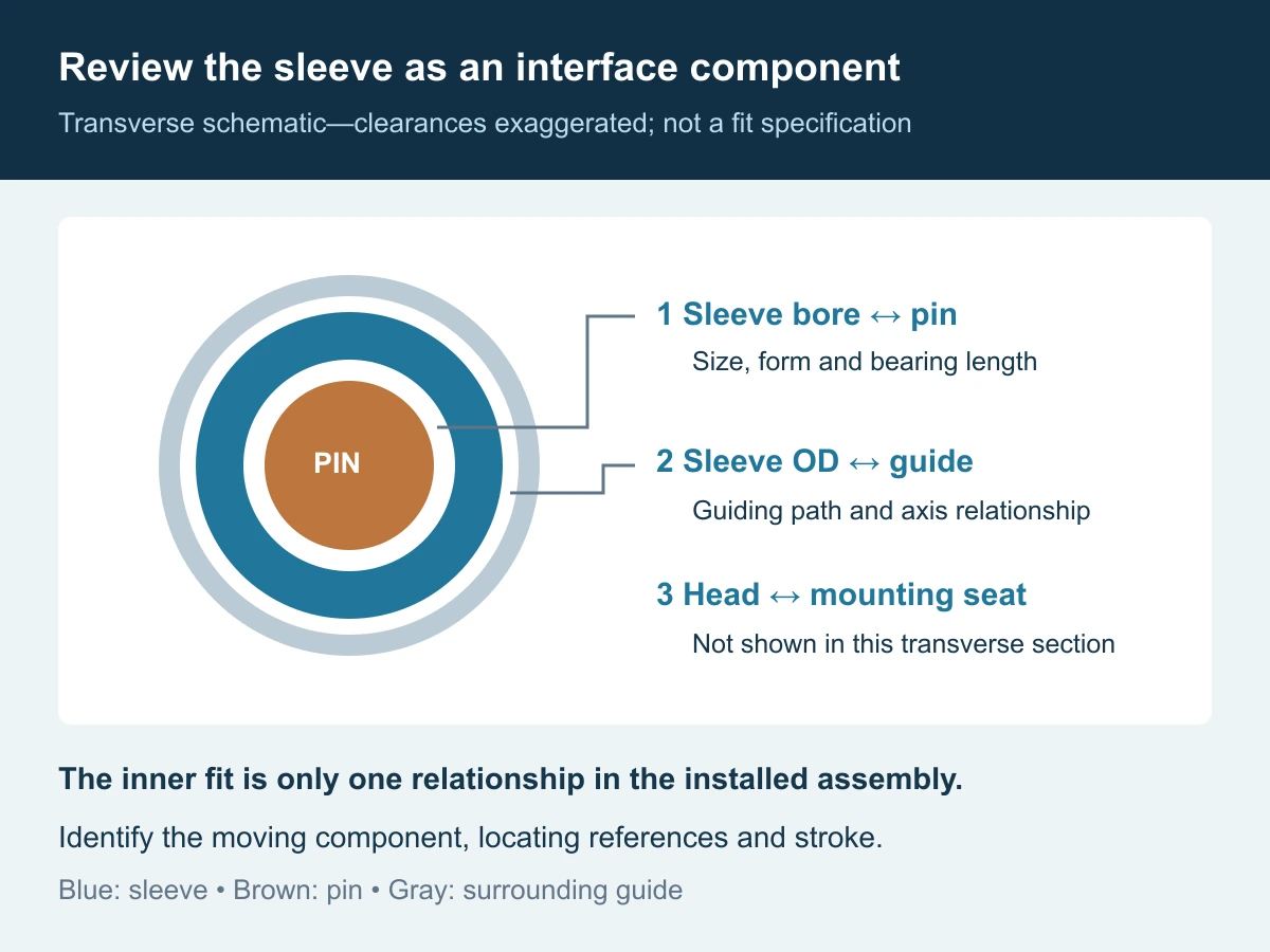
That distinction belongs on the assembly section. Identify which component moves, which is retained, what contacts the plastic and where the sleeve is guided. A part name alone does not establish any of those relationships.
For a moving sleeve around a stationary core, ask the designer to mark the working bore, the outer guiding surface and the head or mounting seat. Also identify the closed position and required stroke. This is more useful for a quotation than a photograph showing only the sleeve’s outside shape.
Why can equal nominal diameters still produce interference?
A nominal size labels a feature; the permissible limits determine the available size combinations. DME explicitly cautions that certain catalog core pins and ejector sleeves are not directly compatible without application-specific modification because their tolerance ranges differ.[2] This is a catalog-specific warning, not a prohibition on designing a compatible custom pair.
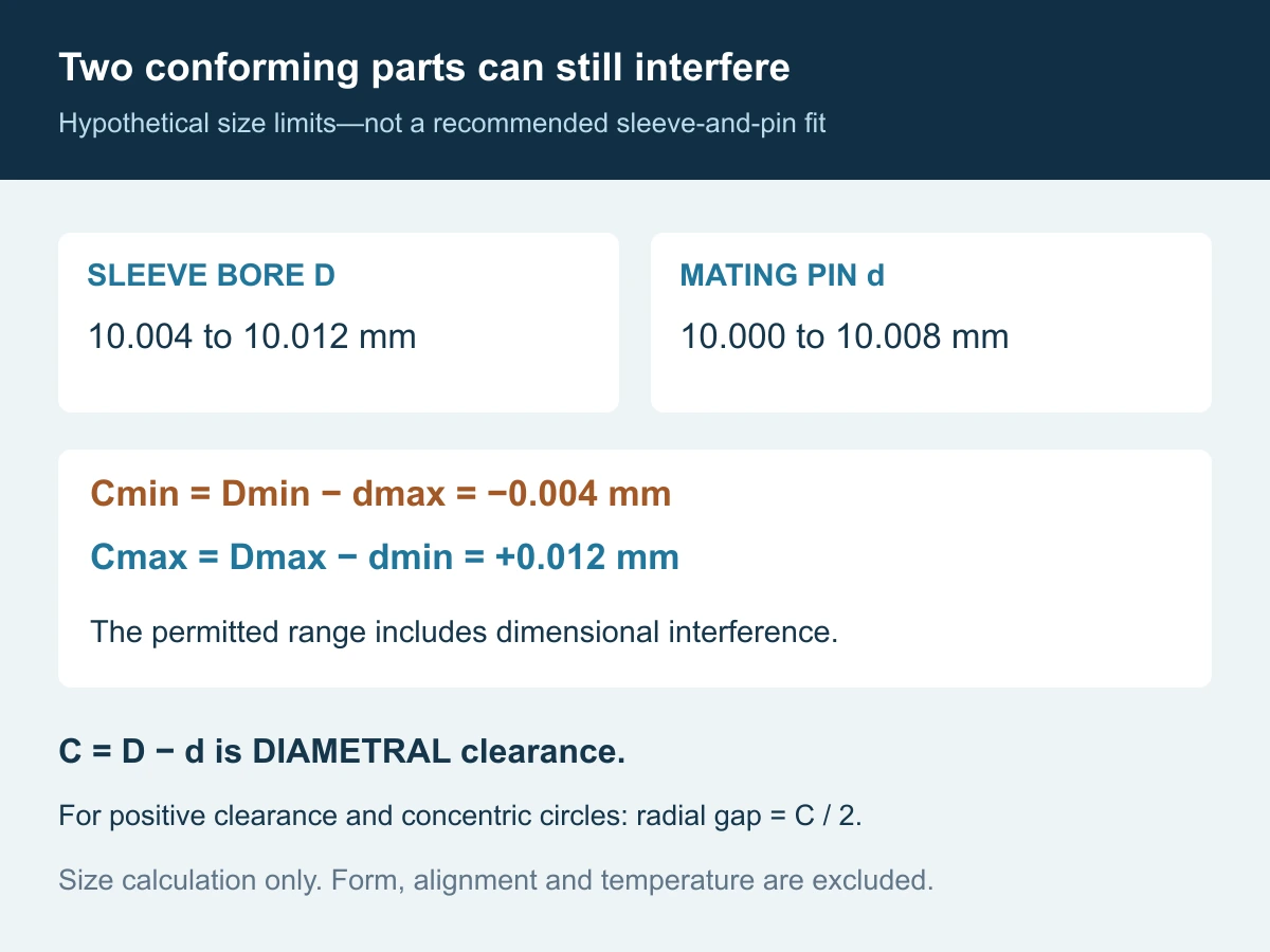
For ideal circular sections, let D be sleeve bore diameter, d be mating pin diameter and C = D − d be diametral clearance. The simple worst-case size checks are:
- Cmin = Dmin − dmax
- Cmax = Dmax − dmin
Here is a deliberately hypothetical specification. It is not a recommended fit:
| Feature | Permitted minimum | Permitted maximum |
|---|---|---|
| Sleeve bore D | 10.004 mm | 10.012 mm |
| Mating pin d | 10.000 mm | 10.008 mm |
| Resulting diametral difference | −0.004 mm at the tightest combination | +0.012 mm at the loosest combination |
The smallest permitted bore with the largest permitted pin gives 10.004 − 10.008 = −0.004 mm. That combination has dimensional interference even though both components satisfy their individual size limits. Conversely, the opposite extremes leave 0.012 mm diametral clearance.
This range is not guaranteed to be a clearance fit. One successfully assembled sample pair would not remove the incompatible combinations permitted by the specification. Either the approved limits must establish the required relationship, or a clearly defined selective-matching arrangement must control which parts may be assembled together.
For a positive clearance between concentric ideal circles, the radial gap is C/2. Do not mix that value with diametral clearance on a drawing or inspection report. This arithmetic checks size only; it does not account for geometric errors, installed alignment, temperature or deformation.
A passing bore-and-pin calculation is not the whole assembly
The sleeve’s inner and outer surfaces connect two locating systems. If the pin axis and the sleeve’s guiding path do not agree, an acceptable diameter difference does not by itself establish free movement over the intended stroke.
DME describes guided ejection as a means of maintaining ejector-assembly alignment and reducing plate cocking and component wear when correctly installed.[3] That is a reminder to include the assembly guidance in the review, not a reason to assume every binding sleeve is caused by the ejector plates.
Our recommended interface review has three parts:
- Inside: which bore length actually bears on the pin, and how are its size, form and surface condition specified?
- Outside: which surrounding feature guides the sleeve, and how is that path related to the pin’s locating references?
- At the head: how is the sleeve retained and driven, and does the seat match the intended mounting arrangement?
Separate working lengths from reliefs and entry features on the drawing. Do not assume that the whole overall length is a precision bearing length, or that one diameter reading describes the bore throughout that length.
Similarly, replace an ambiguous request such as “make it concentric” with the actual geometric requirement and datum reference selected by the responsible designer. The supplier needs a measurable acceptance condition, not a general request for accuracy.
Why a room-temperature hand fit is limited evidence
A clean, low-load bench check can reveal an obvious mismatch. It does not reproduce the installed mounting, alignment, movement or operating temperature. Treat it as a defined check rather than proof of reliable molding operation.
NIST describes 20 °C as the dimensional reference temperature and explains how temperature and thermal-expansion uncertainty affect dimensional measurements made away from that reference.[4] State the reference and measurement conditions when comparing close-fitting components; parts measured under unlike conditions may not provide a meaningful comparison without appropriate treatment of those effects.
For operating fit, consider both components and their constraints. Heating does not automatically close every clearance: relative dimensional change depends on the materials, temperatures and assembly. A freely expanding sleeve bore and a pin do not necessarily change by the same amount. Avoid predicting a hot fit from the mold’s controller setpoint alone.
Also identify the delivered surface state. If a coating or finishing operation affects a mating surface, state whether the reported dimensions apply before or after that operation. Do not accept “coating included” while leaving the final fit undefined. Lubrication and cleanliness requirements should likewise be agreed for the actual application, particularly where product contamination is a concern.
This article intentionally gives no universal running clearance, lubricant or temperature allowance. Those selections require the component geometry, material pair, stroke and operating requirements.
Order an interchangeable spare or an identified matched pair
These are different deliverables. An interchangeable spare should satisfy the approved requirements for the population of mating components covered by its specification. An identified matched pair may be accepted for use together under a controlled pairing arrangement. A matched pair is not automatically interchangeable with every existing pin or sleeve.
For a sleeve-only replacement, supply the mating pin specification and relevant current inspection evidence. Do not ask a supplier to infer the pin’s unworn nominal size from a damaged or worn sample. If the original drawing is unavailable, agree how the intended geometry will be established before manufacture.
| Purchase scope | What must be clear | What should not be assumed |
|---|---|---|
| Sleeve only | Mating pin limits, guide interface and existing condition | A new sleeve will correct a worn pin or misaligned guide |
| Pin only | Actual sleeve specification and approved functional relationship | The same nominal diameter establishes compatibility |
| Matched pair | Pair identification, individual requirements and pair acceptance | Parts may be mixed with other pairs without review |
| Interchangeable spares | Common approved limits and the mating population covered | A single successful hand fit proves interchangeability |
Marking and packaging should preserve any pairing requirement through receiving and maintenance. A technically successful matched set loses its value if the storekeeper reasonably assumes that all sleeves with the same nominal size belong in one interchangeable bin.
Do not describe hand polishing, opening a bore or changing a pin diameter as a routine receiving correction. Such work changes an acceptance surface and may affect the intended relationship. Any modification should follow an approved revision and an agreed reinspection scope.
What should the supplier receive before quoting?
For Huicheng’s custom core pins and ejector sleeves, send the assembly context along with the component drawing. Huicheng can manufacture to customer drawings and help customers prepare drawings; where design inputs are incomplete, agree the drawing-development scope and approve the resulting revision before manufacture.
A useful RFQ package identifies:
- Function and motion: sleeve ejection or another use, moving and stationary components, relevant stroke and closed-position requirements.
- All mating geometry: pin, sleeve bore, sleeve outside, surrounding guide, head seat and functional end face.
- Controlled specifications: size limits, relevant geometric tolerances, bearing lengths, material condition and final surface requirements.
- Assembly conditions: mounting arrangement, known temperatures, relevant lubrication constraints and interfaces outside the supplier’s scope.
- Replacement intent: sleeve only, pin only, matched pair or interchangeable spares; include traceable sample measurements where applicable.
- Acceptance and delivery: report scope, any fit or motion checks, quantity, identification, preservation and required delivery date.
Flag unresolved inputs instead of filling them with assumed catalog defaults. A supplier can quote drawing preparation or further review separately; an incomplete assembly definition should not silently become a fixed manufacturing commitment.
Keep three acceptance decisions visible
We recommend separating the inspection record into three levels. This makes the report more useful when a later problem must be traced to a part, a pair or its installation.
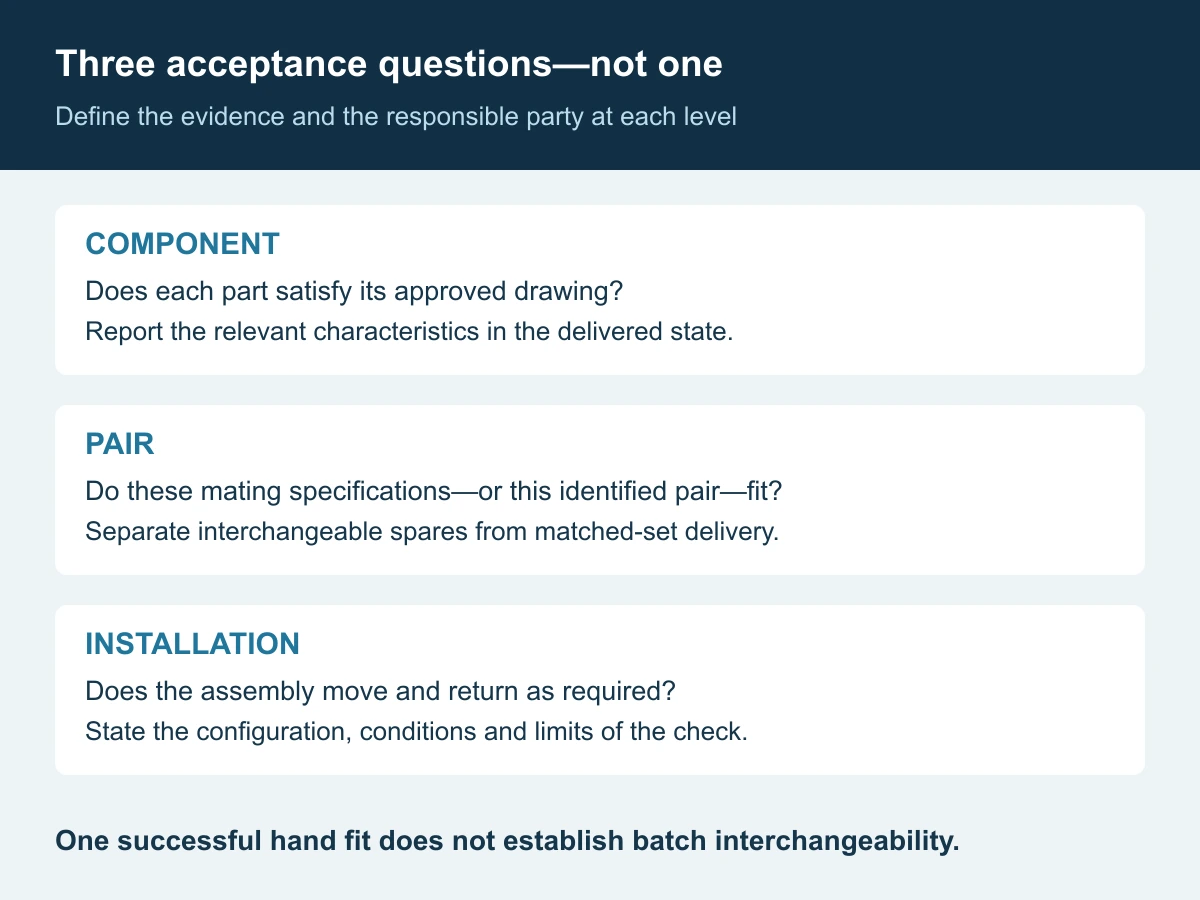
Component conformity: report the specified individual characteristics in the delivered condition. Identify measurement locations and methods appropriate to the bore and pin rather than providing a single unexplained diameter value.
Pair compatibility: confirm the approved fit relationship, or identify the exact matched pair and its agreed checks. Resolve deviations explicitly; selective assembly should not quietly waive individual drawing requirements.
Installed performance: document the agreed movement and return checks in the relevant configuration and conditions. Where molded-part appearance or release is an acceptance requirement, state the trial scope and responsible party. Such testing is not implied merely by ordering two machined components.
All installation, adjustment and motion checks must follow the site’s approved machinery safety procedures. Do not reach into a cycling mold or bypass safeguards to investigate drag or incomplete return.
The practical outcome is a clearer purchase order: who defines the relationship, who verifies the individual parts, and who accepts the assembled result. That clarity prevents a successful inspection report from being mistaken for a promise it never made.
Frequently asked questions
What is the correct clearance between an ejector sleeve and a core pin?
There is no universal value for all assemblies. Specify the required relationship from the actual geometry, motion, materials and operating conditions, then check the complete allowed size range. The numerical example above is not a recommended fit.
Is a tighter fit always better for preventing flash?
No. The assembly must satisfy both the required molding-surface condition and its intended movement. Reducing a clearance without resolving the full relationship can create another problem. Have the responsible designer approve the final requirement.
Can a standard core pin be used inside a standard ejector sleeve?
Only after checking the exact product drawings and application. The catalog family, size convention, tolerances and working geometry matter; neither the word “standard” nor equal nominal diameters establishes compatibility.
Does one pair sliding smoothly prove a batch will assemble?
No. It describes that pair under those check conditions. Batch interchangeability requires compatible specifications and an agreed verification plan; matched-set delivery requires traceable pairing.
References and scope notes
Primary sources support the specific principles cited. The hypothetical tolerance example, purchasing tables and acceptance framework are editorial guidance, not Huicheng case data or guaranteed capabilities. Catalog-specific dimensions and product claims have not been adopted as universal specifications.
- DME: Imperial Pins catalog, Ejector Sleeves section — distinguishes sleeve ejection and bushing applications. ↩
- DME Components FAQ: using core pins with ejector sleeves — catalog-specific tolerance compatibility warning. ↩
- DME: Guide Pins for Guided Ejection — alignment and ejector-plate guidance context. ↩
- NIST: Uncertainties in Dimensional Measurements Made at Nonstandard Temperatures — dimensional reference temperature and thermal-expansion uncertainty, not a mold operating-clearance prescription. ↩