A mold shutoff insert should be specified as one side of a functional interface—not just as a loose steel component. Before ordering, identify the opposing surface, the intended contact region, any approved fitting allowance, and the molded-part criteria that will establish acceptance. An insert can meet its drawing dimensions while the assembled mold still produces unacceptable flash.
The missing information is often not a tighter tolerance. It is the relationship between the purchased insert, retained tooling and molding conditions. This guide helps tooling buyers define that relationship for thermoplastic injection molds. It concerns mold sealing faces, not machine shutoff nozzles or hot-runner valve gates.
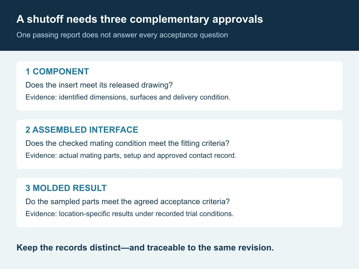
Separate three approvals: the insert meets its drawing; the assembled interface meets the agreed fitting criteria; and molded parts meet acceptance under the recorded trial conditions. Evidence for one does not automatically establish the other two.
What does a shutoff surface do?
A shutoff is a meeting of mold faces that blocks resin from entering an unintended region. Depending on the geometry, it can help form a hole, window or other opening in the plastic part. Protolabs demonstrates sliding shutoffs that meet as the mold closes and explains how draft reduces rubbing and wear during their relative movement.[1]
That principle does not create one universal shutoff angle. Protolabs gives a three-degree minimum in the examples covered by its design guidance; treat that as application-specific guidance, not an automatic Huicheng specification. The actual design must identify the opening direction, local geometry and intended engagement. A general part-wall draft note is not necessarily a complete definition of the steel-to-steel interface.
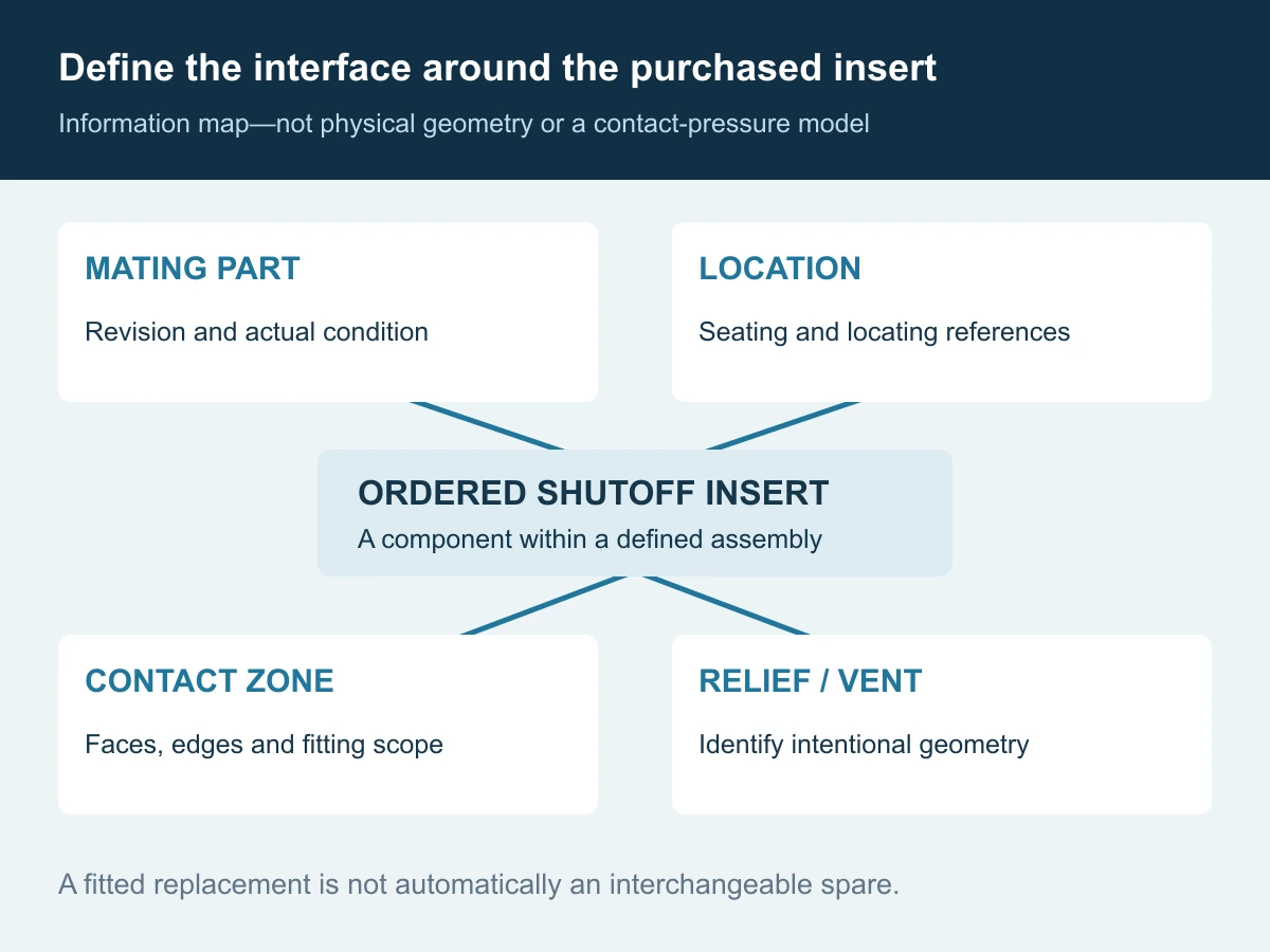
For purchasing, mark which faces form plastic, which locate or support the insert, which provide shutoff contact and which are intentionally relieved. Do not ask a supplier to infer these roles from an unannotated solid model. Where a vent intersects the interface, identify it separately: an intentional vent feature must not be removed merely because it resembles a gap.
Do not use “flash” to describe every line or step
The complaint needs a measurable definition before it becomes a machining instruction. Protolabs distinguishes the parting line associated with the mold split from the possibility of resin escaping at that seam.[2] A visible line is not, on its own, proof that a shutoff has failed.
| Observed feature | Describe it as | Acceptance question |
|---|---|---|
| A thin unwanted extension beyond the intended part boundary | Suspected flash; document the section and location | What protrusion, thickness or extent is permitted, and how is it measured? |
| A step between adjacent molded surfaces | Mismatch or offset | What step is permitted across the identified junction? |
| A line or visual transition at a mold split | Parting or witness line, pending inspection | Is the appearance acceptable in the defined viewing zone? |
| Damage visible only after trimming | Post-processing condition | Is acceptance as-molded or after an approved finishing operation? |
These conditions can coexist. Use tagged samples, a marked drawing and suitable measurements rather than relying on a photograph with no scale. State the reference surface and measurement direction. A protrusion into a connector opening, for example, may need a functional acceptance check different from a cosmetic seam on an exterior wall.
A blanket “no flash” note can be ambiguous unless the inspection method, locations and limits are defined. Equally, a general allowance should not silently authorize material inside a critical opening. Establish local requirements before machining or quotation approval, not after the first sample becomes a disputed reference.
Specify the pair, even when buying only one insert
The supplier needs enough information to understand the interface it cannot see. At minimum, the package should identify the purchased detail and the retained mating part by revision and location. Add a section through the critical shutoff where a single view does not make the intended contact clear.
- Contact region: mark the surface intended to shut off and the edges that must be preserved.
- References: identify the seating and locating features that place that surface in the assembly.
- Opposing condition: provide the mating drawing and relevant actual-condition information for retained tooling.
- Movement: show the applicable opening direction and any relative sliding engagement.
- Relief and venting: distinguish intentional non-contact areas and approved vent geometry.
- Delivery condition: state whether the surface is finished to size or supplied with a defined fitting allowance.
For a replacement, separate original design intent from wear. Copying the current shape of a damaged insert can reproduce a defect rather than restore the intended interface. If the mating surface has changed, the buyer must decide whether the order is a replacement to the original specification, a fitted replacement for that particular mold, or a coordinated repair.
A useful allowance instruction identifies the face, amount and direction, the final target, who may remove the stock and who approves the result. “Leave steel safe” without those details transfers the decision downstream. Do not assume a locally fitted component is interchangeable with every nominally identical spare.
Why a new insert or more clamp force may not resolve flash
BASF’s thermoplastic troubleshooting guide identifies several possible contributors to flash: insufficient clamping, excessive fit gaps, damaged sealing faces, excessive cavity pressure, low melt viscosity and mold deformation under pressure.[3] The observed location matters, but it does not uniquely identify the cause.
Autodesk describes the calculated clamp force as the resultant of the pressure distribution acting to open the mold during filling and packing.[4] Our practical interpretation is that a total force value and the local condition of a particular interface answer different questions. Neither a machine’s nominal tonnage nor a simulation result is a stand-alone certificate of acceptable shutoff contact.
Build an event record before selecting a correction. Note whether the issue existed from initial sampling, appeared after insert replacement or maintenance, followed a resin or process change, or developed during a run. Keep cavity and location identities separate. These observations guide investigation; they do not establish causation by themselves.
For example, suppose flash appears after a new insert is installed. Review its dimensions, seating and mating condition, but also record whether the setup changed. If geometry and processing were both revised, the timing alone cannot isolate which change caused the result. This is an illustrative review scenario, not a Huicheng customer case.
Do not prescribe increased clamp force, lower temperature or hand polishing as a universal remedy. The responsible molding and tooling teams should evaluate changes against resin guidance, equipment limits and part requirements. Inspection and fitting must follow the site’s authorized isolation and mold-handling procedures. Never reach into a cycling mold to investigate a contact line.
What evidence should be required before release?
1. Component inspection: does the insert meet the released definition?
Check the specified references, relevant profile and position, surface condition and any intentionally retained allowance. Reports should identify the part and revision. If only the purchased insert was measured, do not label the report as verification of the complete assembled interface.
2. Assembly verification: what was checked against the actual mating tooling?
Agree the assembly and contact-check method, including which mating parts are used and the checking condition. If a spotting or contact-transfer method is specified, retain a location-marked record and agreed acceptance criteria. An attractive contact photograph without its setup and interpretation rules is weak purchasing evidence.
A static contact indication records the condition checked. It does not by itself reproduce the resin pressure, temperature and production history of a molding cycle. Nor should material be removed from every marked high spot without reviewing the intended support and sealing functions. Record any authorized fitting and the resulting dimensions.
3. Molding validation: do the parts meet the agreed criteria?
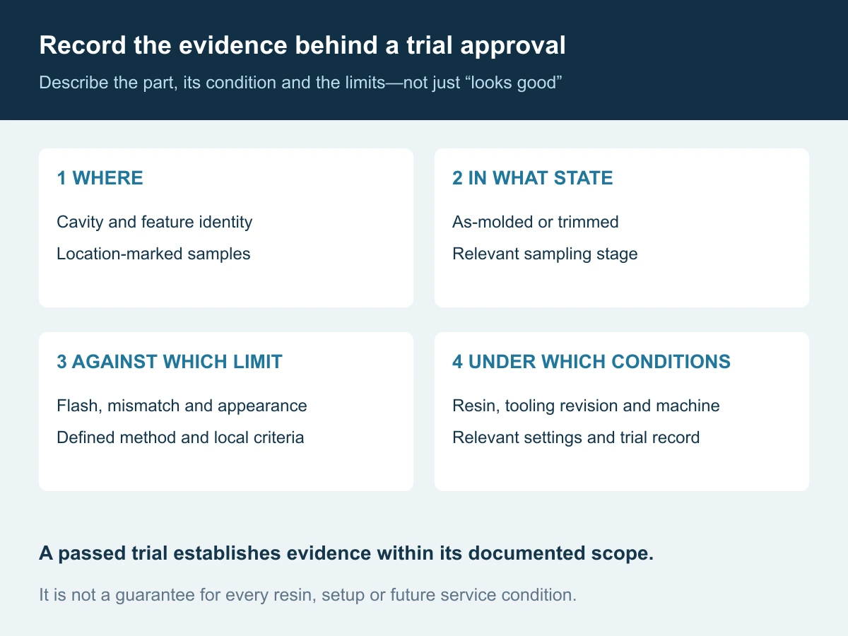
Identify the resin grade and condition, mold and insert revisions, machine, relevant settings, sampling stage and cavity. Inspect flash, mismatch and appearance separately at the designated locations. Record whether samples are as-molded or trimmed; otherwise a finishing operation can conceal the condition being evaluated.
Agree representative trial conditions and sampling rather than declaring success from one attractive part. If an issue previously appeared after warm-up or after maintenance, include that relevant state in the evaluation plan. No universal cycle count is prescribed here, and a passed trial is not an unlimited guarantee for every resin or process setting.
Match the quotation to the actual responsibility
There are three different scopes a buyer might mean by “supply a shutoff insert.” Make the intended one explicit:
| Supply scope | Define in the quotation | What must not be assumed |
|---|---|---|
| Component to released drawing | Material condition, geometry, finish, inspection and delivery state | Fitting to unavailable mating tooling or a production-result guarantee |
| Component with agreed fitting work | Access to mating parts, allowable adjustments, final records and approval | Interchangeability beyond the tested configuration |
| Coordinated correction and molding validation | Affected tooling, trial resources, resin, criteria, deliverables and responsibilities | Unlimited process development or acceptance outside the agreed trial scope |
For Huicheng’s custom precision mold inserts, send the controlled drawing or available design information together with the mating-interface details and the intended supply scope. Huicheng can manufacture to customer drawings and help customers prepare drawings. Where information is incomplete, agree what must be measured or developed and approve the resulting requirements before manufacture.
Fitting, access to customer tooling, specialist inspection and molding-trial arrangements should be reviewed and quoted for the specific project. They are not automatic inclusions in every insert order. A quotation should identify outstanding inputs rather than quietly treating them as someone else’s responsibility.
The release package should connect the three approvals: manufactured geometry, assembled relationship and accepted molded output. Keeping those records separate but linked makes it easier to resolve a problem, assign the right corrective work and reorder the correct spare.
Frequently asked questions
Is a shutoff surface the same as the entire parting surface?
Not necessarily. Identify the local faces performing the sealing function and their relationship to the mold split. Do not treat every nearby surface as requiring the same contact, relief or finishing condition.
Can CMM inspection prove an insert will produce no flash?
No. It can verify the measured geometric characteristics. Assembly contact and molded-part performance need evidence appropriate to those questions.
Does a visible parting line always mean the mold needs repair?
No. First distinguish a normal junction mark, mismatch and excess material. Evaluate the actual feature against the agreed cosmetic and functional criteria.
Should the supplier always leave extra stock on a shutoff?
No. The delivery condition depends on the agreed manufacturing and fitting route. Any allowance needs a defined location, amount, final target and responsible party.
References and scope notes
These primary sources support the specific technical principles cited. The RFQ tables, acceptance framework, illustrations and example are editorial guidance, not a company case study, mandatory inspection standard or universal mold-setting procedure.
- Protolabs: Incorporating Shut-offs in Injection Molding Design — shutoff function and draft in its illustrated straight-pull applications; its numerical guidance is not a universal specification. ↩
- Protolabs: Cosmetic Defects in Injection Molding — the section on flash and parting lines. ↩
- BASF: Injection-Molding Problems in Engineering Thermoplastics, section 09, Flash — multiple tool, machine and material/process contributors. No blanket processing adjustment is prescribed here. ↩
- Autodesk Moldflow Help: Clamp Force Result — pressure-resultant meaning of the calculated force; not proof of local shutoff contact or Huicheng simulation capability. ↩