“Use 8% clearance” is not a complete instruction for a stamping-tooling supplier. If one person means clearance per side and another means the total difference between punch and die sizes, both can follow the instruction—and produce different tools.
A second problem is less obvious: the measured punch and die sizes may give the intended average clearance, while misalignment leaves one side too tight. Ordering a sharper punch or a harder tool steel will not automatically correct either problem.
Specify punch and die clearance as a defined per-side gap at the cutting edges, identify the sheet material and thickness range, and state whether the operation is piercing or blanking. For a centered round pair, die opening diameter equals punch diameter plus twice the per-side clearance. Coordinate component tolerances and assembly alignment, then verify the stamped result against agreed dimensional and edge-quality criteria. There is no single clearance percentage suitable for every material and operation.
1. Define clearance at the cutting edges
Per-side clearance is the gap between the punch cutting edge and the corresponding die cutting edge. It is not the punch-to-stripper clearance, guide-bushing fit or relief farther down the die opening. Those dimensions have different functions.
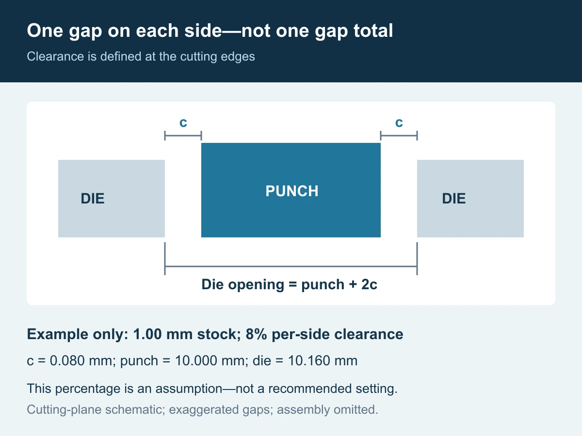
For a centered circular punch and die, use:
Ddie = Dpunch + 2c
c is clearance per side. The diametral difference is 2c. Use consistent units.
MISUMI’s button-die selection data explicitly uses the punch diameter plus twice the clearance to calculate the die opening.[1] The geometry is straightforward; the specification must still identify the intended convention.
Illustrative calculation, not a recommended setting: assume a 1.00 mm sheet, a 10.000 mm punch and an approved clearance of 8% of sheet thickness per side. Then c = 0.080 mm and the nominal die opening is 10.160 mm. If “8%” is mistakenly treated as the total diametral difference, the die becomes 10.080 mm and the per-side clearance is only 0.040 mm.
Write both the per-side value and its basis on the release document. For nonround profiles, define the offset around the cutting contour and review corner transitions; subtracting only an overall width and length does not establish the local clearance everywhere.
2. Identify which piece is the product: piercing or blanking?
Two operations can look similar at the press while requiring a different dimensional starting point:
| Operation | What is retained? | Basic tooling-size relationship |
|---|---|---|
| Piercing a hole | The surrounding sheet with the required opening | Start from the required hole and punch relationship; the die opening is larger by the specified clearance |
| Blanking an outside contour | The piece cut out of the sheet | Start from the required blank and die-opening relationship; the punch is smaller by the specified clearance |
MISUMI’s blanking tutorial explains the basic convention of sizing the die to the blank and reducing the punch for clearance.[2] These are design starting relationships, not guarantees that every measured section of the cut product will exactly equal a tool dimension.
Elastic recovery, the cut-edge profile, wear allowance and the product’s measurement definition still matter. A pierced hole can have different apparent dimensions at its entry, burnished region and fracture region. Specify the feature and acceptance method instead of assuming that one nominal diameter describes the entire edge.
This guide concerns conventional sheet-metal piercing and blanking. Fine blanking, shaving and other special edge-finishing operations require their own tooling and process criteria; do not transfer this guide’s illustrative percentage into them.
3. Choose a starting clearance from the material and the required result
“Stainless steel, 1 mm” leaves important questions open. Identify the grade, supply condition, relevant strength information and actual thickness range. Also identify small holes, narrow webs and corner features that may need separate review.
Dayton Lamina bases its engineered-clearance guidance on material type, strength, thickness and job requirements, rather than one historical rule of thumb. It also describes applications where increased clearance improves performance.[3] This supports evaluating the actual application—not making every gap smaller, or making every gap larger.
For the buyer, the useful deliverable is a proposed clearance with a stated basis and an acceptance plan. Ask what it is intended to balance: part dimensions, burr height, cut-edge condition, stripping behavior and maintenance interval.
A fixed tool gap also represents different percentages when stock thickness changes. With c = 0.080 mm, it equals about 8.42% of a 0.95 mm sheet and 7.62% of a 1.05 mm sheet. This arithmetic does not predict a defect; it shows why the approved material range belongs in the tooling specification.
Avoid demanding a universal amount of shiny shear surface as proof of quality. A functional assembly edge, a cosmetic edge and an edge that will later be formed or deburred may have different requirements. A maximum burr value alone may not capture the result the downstream process needs.
4. Correct nominal clearance can conceal a local interference risk
A clearance calculation from two diameters assumes that the punch and die are centered. It does not prove that they will be centered when installed or loaded.
Illustrative geometry: take the nominal 0.080 mm radial gap above. If the punch center is displaced 0.030 mm from the die center, the opposing gaps along the line of displacement become 0.050 mm and 0.110 mm. The diameter-based average remains 0.080 mm.
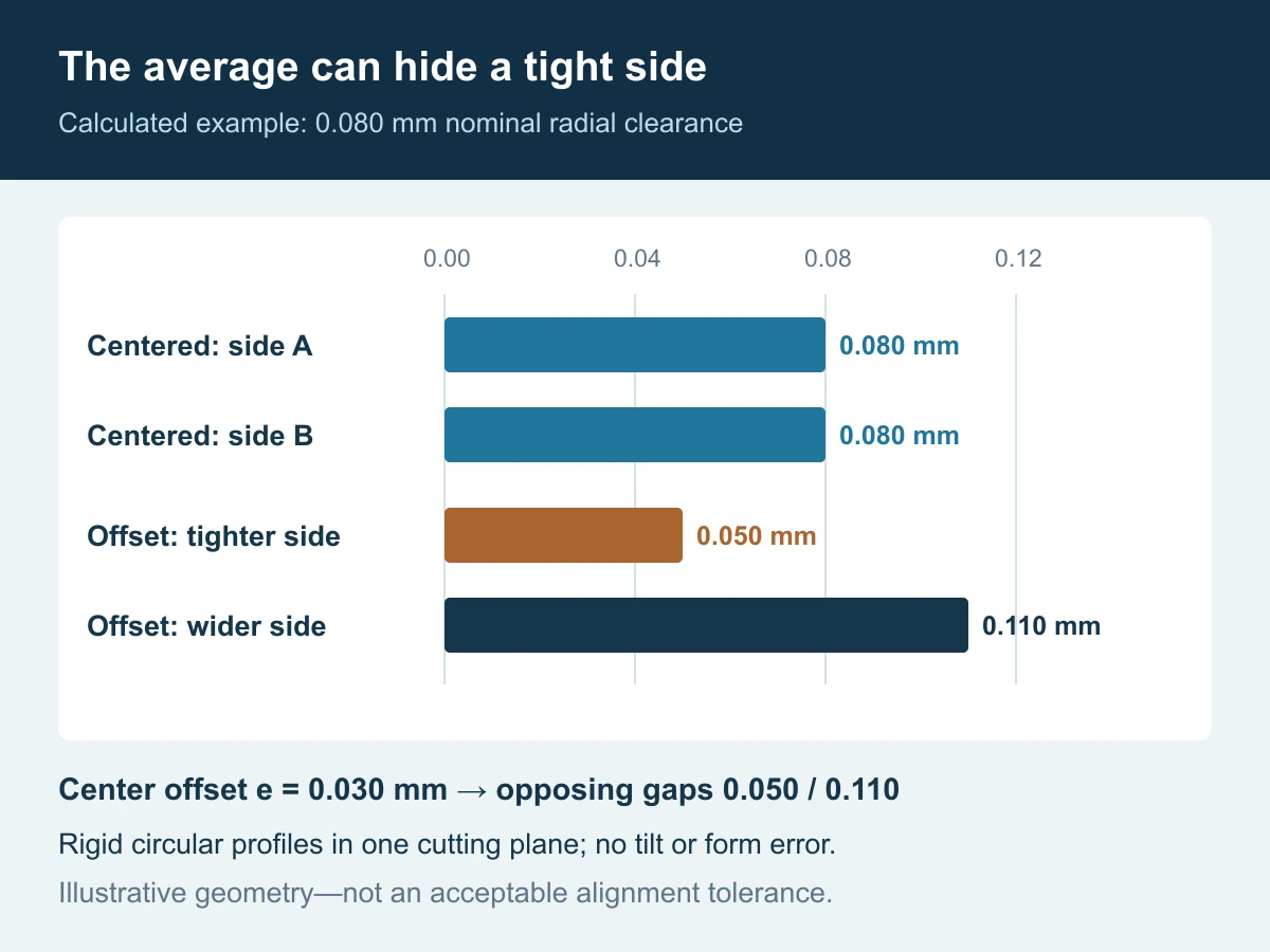
For this simplified geometry, a useful screening expression is:
e is the center offset at the cutting plane. This expression assumes circular profiles without tilt, form error or load-dependent movement.
Do not use the expression as a complete die validation. Profile error, angular misalignment, guidance, mounting and press/tool deflection may change the gap during operation. Its purchasing value is simpler: component size tolerances and installed alignment must be reviewed together.
When a supplier proposes tighter manufacturing tolerances, ask which uncertainty they reduce. Better profile accuracy is useful, but it cannot by itself repair a worn locating system or establish the behavior of an unsupported assembly under load.
5. Treat the cut edge as evidence, not a one-step diagnosis
Uddeholm describes the conventional cut edge in terms of rollover, burnish, fracture and burr. Its advanced-high-strength-steel guidance also illustrates a tradeoff between clearance, edge quality, galling, wear and chipping risk.[4] Recommendations for a particular sheet grade should not be generalized to every metal.
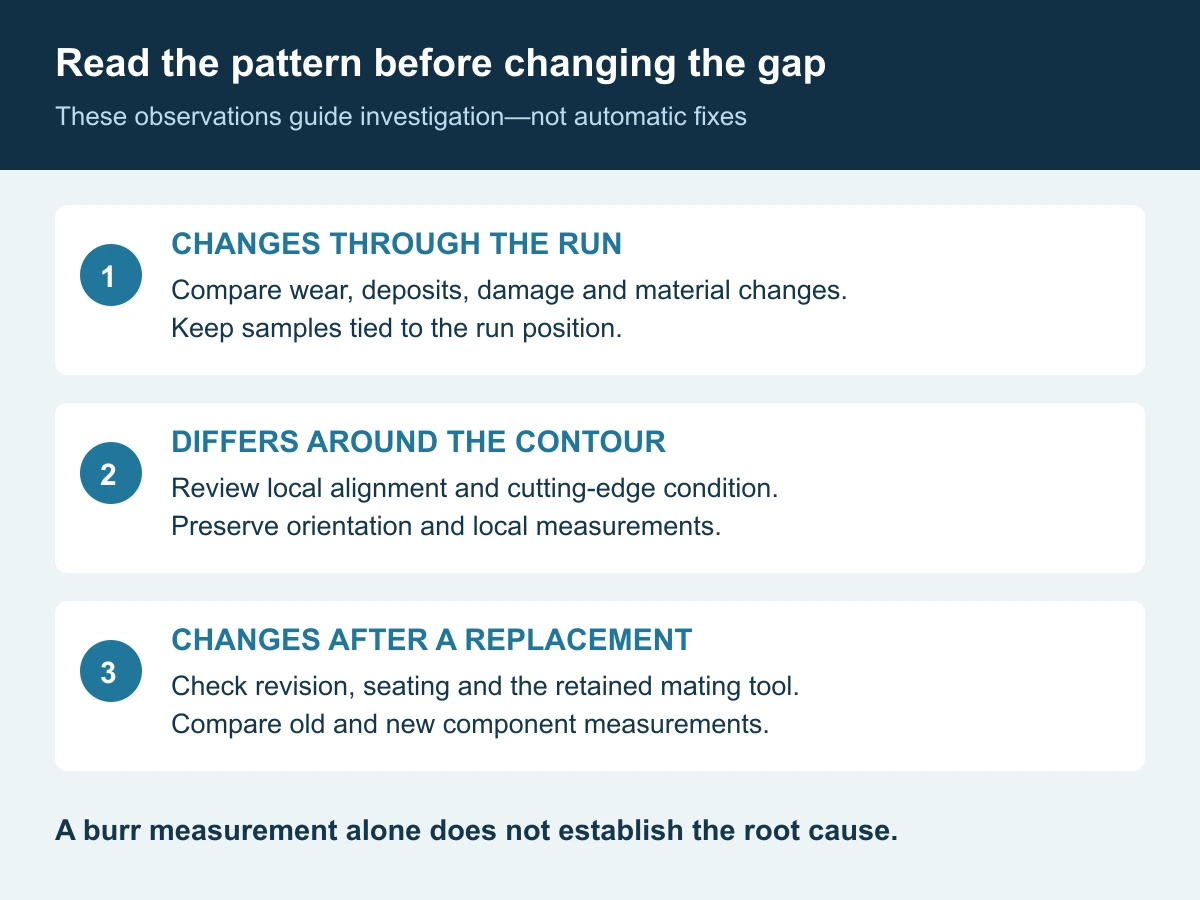
Use the following observations to decide what to inspect next. They are not automatic root-cause assignments.
| Observed pattern | Check before changing clearance | Evidence to preserve |
|---|---|---|
| Burr increases progressively during a run | Cutting-edge wear, adhered material, damage and any material/process changes | Part samples tied to run position and edge-condition records |
| Burr or edge appearance differs around the profile | Local alignment, profile condition and unequal wear | Orientation-marked samples and local measurements, not just an average |
| A replacement immediately changes edge quality | Part revision, actual mating dimensions, seating and supplied condition | Old/new tool measurements and the unchanged mating component |
| Scrap returns with the punch or fails to clear | Slug control, punch entry, stripping and scrap path as well as the gap | Safe observations by qualified personnel and the relevant assembly details |
Dayton’s perforating guidance identifies punch overentry and withdrawal-related effects as contributors to slug-pulling problems.[5] A clearance change alone may therefore leave the actual mechanism unresolved.
Record which side of the product carries the burr and where it is measured. State whether acceptance is before or after deburring. Inspection and tool adjustment must follow the site’s safe press and tooling procedures; never reach into an operating press to investigate an edge or slug problem.
6. Decide whether to replace the punch, the die or a coordinated pair
Replacing only the worn component can be reasonable if the retained component and locating system remain suitable. Supplying a new pair can be reasonable when both cutting profiles need renewal. Neither option should be selected only from the price of one replacement part.
- Punch only: provide the retained die’s actual cutting profile and condition, not merely the old purchase description.
- Die only: verify the punch that will run with it, including local wear and the relevant reference features.
- Coordinated pair: define the clearance, mounting references and whether the parts are matched to each other or intended to interchange with other sets.
A matched pair is not automatically interchangeable with every existing tool of the same nominal size. Identify the pairing where necessary. Likewise, do not alter the punch diameter solely to restore a gap without checking whether the change affects the required pierced feature.
For reground tooling, confirm the resulting working lengths, cutting-land condition and assembly relationship. If a coating is specified on the mating cutting profiles, define whether acceptance dimensions apply after that coating. The replacement should be accepted in the condition in which it will be installed.
7. Send an RFQ that can be manufactured and verified
Huicheng supplies custom stamping die components, including punches, dies and stripper plates. Huicheng can manufacture from customer drawings and can also help customers prepare drawings. For a replacement or coordinated pair, include the mating information needed to define the component correctly.
- Operation and product: piercing or blanking, retained part, controlled product drawing and critical edge requirements.
- Sheet specification: grade, condition, thickness range and available strength information.
- Tooling geometry: controlled profiles, corner details, reference features, mounting and relevant assembly sections.
- Clearance: per-side value, percentage basis if used, approved limits and applicable cutting regions.
- Supply scope: punch only, die only or coordinated pair; material, hardness, finish and final coated/uncoated condition.
- Evidence: required inspection records, existing tool measurements and orientation-marked samples where a problem is being investigated.
- Release plan: quantity, timing, drawing approval, assembly checks and any agreed stamping trial.
Separate component acceptance from process acceptance. A dimensional report can establish the supplied geometry; it does not prove the cut edge on the customer’s press with the customer’s material. If a trial is required, agree the material, equipment, sample criteria, responsibilities, cost and timing. Do not assume trial stamping is included in every component quotation.
When drawings are incomplete, send available sketches, samples and mating-part information. Agree the drawing-assistance scope and approve the release before manufacture. Copying a worn cutting edge without identifying the intended geometry can reproduce the problem.
Buyer questions
What is the correct punch and die clearance percentage?
There is no universal number. Use material- and operation-specific guidance as a starting point, with the convention stated explicitly, then validate against the required edge, dimensions and tooling performance.
Does a smaller gap always produce a better edge?
No. A change may improve one characteristic while worsening stripping, wear or another edge characteristic. Evaluate the complete requirement rather than treating minimum clearance as maximum quality.
Can we calculate clearance from punch and die measurements?
Yes, for the defined geometry. For a round pair, half the diameter difference gives the nominal radial gap. It does not establish the minimum installed gap unless alignment and form are also accounted for.
Must the punch and die be ordered together?
No. A single replacement can work when the retained tooling is measured, suitable and correctly identified. A coordinated pair can simplify matching, but the assembled tooling still needs appropriate checks.
Sources and footnotes
The numerical examples and procurement checklists are original explanatory tools, not supplier quotations, production tests or universal clearance specifications. Sources below support the specific principles cited.
- MISUMI. Selection of Button Dies. Per-side convention and the relationship between punch diameter and die opening. Back to text ↑
- MISUMI Technical Tutorial. Basics of Blanking Work: Blanking Work. Retained blank and basic die/punch dimensional relationship. Back to text ↑
- Dayton Lamina. Dayton’s Engineered Clearance. Material, thickness, strength and application-specific clearance selection; its proprietary recommendations are not Huicheng guarantees. Back to text ↑
- Uddeholm. Tooling Solutions for Advanced High Strength Steel, printed pages 18–19. Cut-edge regions and material-dependent clearance/tool-life tradeoffs. Back to text ↑
- Dayton Lamina. Improving Perforating Die Performance. Punch entry, withdrawal and slug-control considerations beyond clearance alone. Back to text ↑