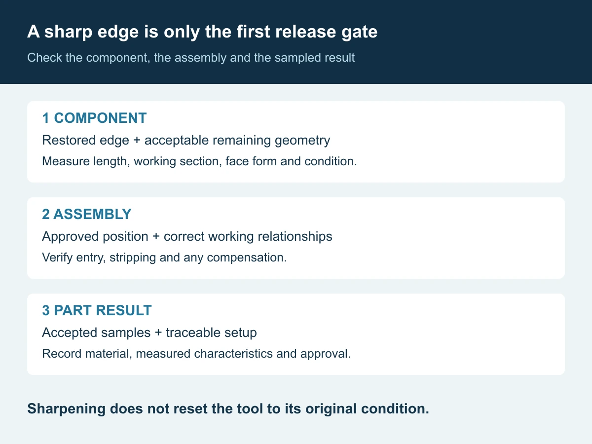
A reground punch can look sharp and still be wrong for the die. Removing stock from the cutting face changes the component’s length; restoring its installed height does not restore the steel that was removed. For buyers and maintenance teams, the useful question is therefore not “Can it be sharpened?” but “Can it be returned to the approved working condition, with enough usable geometry left?”
Quick answer: Regrind only when the damage can be removed within the tool’s approved dimensional and condition limits. Then verify the assembled penetration, stripping relationship and part result. Replace or hold the component when those limits are exceeded, damage is unresolved, or the remaining geometry cannot be established. A sharper edge alone is not a release criterion.
This guide addresses cutting punches and mating dies, particularly custom stamping components. It is not a grinding recipe or a machine setup instruction. Catalog limits for a particular turret-tooling system must not be transferred to a different progressive die or custom punch. Tool changes and setup checks belong to qualified personnel following the machine’s isolation and safety procedures.
1. Separate a worn edge from a system problem
A rising burr is a reason to investigate, not proof that another sharpening cycle is the complete answer. Record where the burr occurs, whether wear is symmetric, when it appeared and whether the material or setup changed. Compare the punch with its mating die before issuing a regrind order.
Dayton Lamina’s troubleshooting guide identifies alignment, clearance, sharpening damage and grinding burrs among potential contributors to punch problems. It also lists both excessive and insufficient punch entry as possible contributors to slug pulling. That is why “increase penetration” is not a universal correction.[1]
For the buyer, this creates two separate work scopes: restore a serviceable component, and resolve any cause that will damage it again. A regrind quotation should not quietly become approval to change clearance, punch material or die geometry. Conversely, a replacement order should not assume that a new punch will correct a damaged guide or worn mating die.
| Observed condition | Question before authorizing work | Useful evidence |
|---|---|---|
| Gradual, reasonably uniform edge wear | Can the edge be restored within the approved remaining geometry? | Wear photographs, measured length and intended stock removal |
| Localized chipping or one-sided wear | Is there an unresolved contact, support or alignment issue? | Marked damage location and inspection of mating components |
| Suspected crack or thermal damage | Is there an approved disposition, rather than a cosmetic cleanup? | Condition assessment and the agreed inspection method |
| Acceptable edge but repeated production defects | Is the defect actually linked to setup, stock or the mating tool? | Traceable samples and the corresponding setup record |
2. Define remaining grind life in dimensions, not sharpening counts
“Sharpened five times” is weak information. Five light touch-ups and five deep chip-removal operations can leave very different tools. Track cumulative removal, but base the decision on the actual geometry that remains.
Mate’s Murata Wiedemann catalog publishes different minimum overall lengths and grind-life limits for different tooling styles and stations. It also relates straight-before-radius geometry and allowable grind life to the application. These are examples of system-specific limits—not a universal allowance for Huicheng components or custom dies.[2]
A practical custom-tool drawing or maintenance sheet should identify:
- The reference surface used to measure punch length, and the minimum permissible length.
- The required working section before a shoulder, radius, taper or other transition.
- The mating die’s remaining cutting land, minimum height and any retention features affected by grinding.
- The approved compensation method and its limits, if compensation is permitted.
- The face form, edge preparation and inspection criteria after regrinding.
Do not confuse overall length with usable cutting geometry. A holder adjustment may restore the tip position, while the shoulder is now too close to the working region. Likewise, raising a die may restore its top surface but cannot recreate a consumed cutting land. For a die whose relief begins immediately below the cutting face, face grinding may expose a different opening size; check the actual design rather than assuming a parallel land exists.
If a worn sample is the only available reference, mark current dimensions as measured condition. Do not silently adopt them as the original design. Establish the intended geometry from mating parts, accepted parts, previous records and an approved drawing before manufacturing a replacement.
3. Recalculate punch entry when either cutting face moves
Length compensation and die penetration are related, but they are not the same measurement. Penetration is the punch tip’s position relative to the die’s cutting surface at a defined point in the stroke. It is not simply punch overall length or the amount removed by the grinder.
For a flat-face, rigid stack with unchanged backing references and unchanged bottom position, use the following signed bookkeeping relationship:
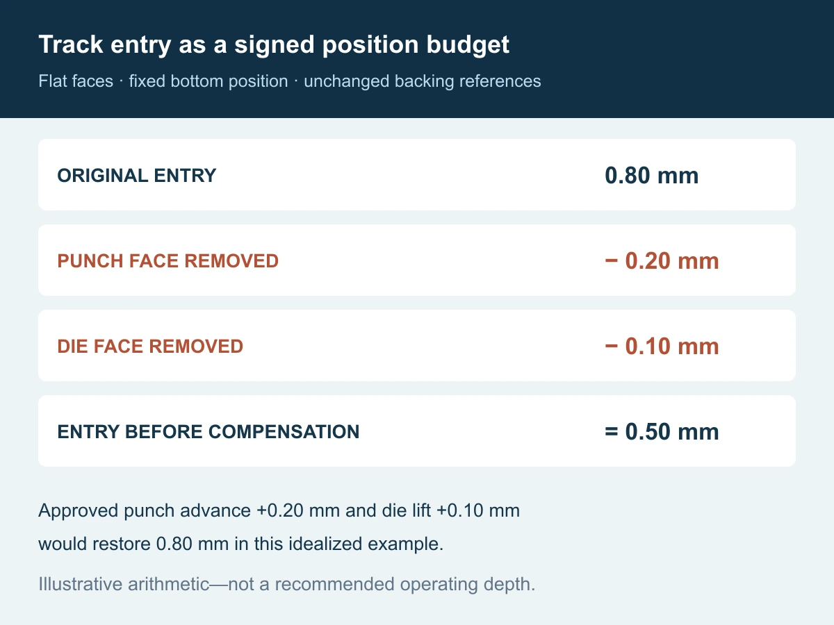
New entry = original entry − punch-face removal − die-face removal + punch advance + die lift.
“Punch advance” means an approved adjustment that moves the tip farther toward the die. “Die lift” means an approved adjustment that raises the die’s cutting surface toward the punch. All terms are measured along the stroke axis. This simplified relationship excludes deflection, thermal movement and changes elsewhere in the stack.
Illustrative arithmetic, not a setup recommendation: suppose the original entry is 0.80 mm. Removing 0.20 mm from the punch face alone reduces it to 0.60 mm. If 0.10 mm is also removed from the die face without lifting the die, the resulting entry becomes 0.50 mm: the die’s cutting surface is now lower, reducing the depth reached below it. Restoring punch projection by 0.20 mm and die height by 0.10 mm returns the idealized entry to 0.80 mm. None of these values is a recommended operating depth.
The important distinction is that grinding both cutting faces does not cancel out: with fixed backing references, the two removals add to the loss of entry. Correcting that entry still does not, by itself, prove correct strip support or stripper operation.
UniPunch notes that reground dies may need shims to maintain uniform die height.[3] In a custom die, any shim or adjustment still needs design approval, adequate support and a check of the affected interfaces. Do not lower the whole press setup to compensate for one shortened punch without reviewing the other stations.
4. Specify the condition after grinding—not just the amount removed
An instruction such as “remove 0.10 mm” tells the supplier how much stock to take off. It does not establish whether damage has been removed, whether the face form is correct or whether the edge meets its acceptance criteria. Agree what happens if inspection shows that the authorized removal is insufficient.
Mate’s maintenance guidance emphasizes suitable grinding practice, coolant and removal of grinding burrs. It also warns that visible burn discoloration may represent damage beyond the surface: removing the colored layer does not establish that the tool is sound.[4] Hold a suspect tool for an approved disposition; do not use appearance alone to release it.
The purchase or maintenance instruction should retain the specified shear face, orientation, flatness and edge preparation. “Sharp” must not become permission to remove a designed shear form or to apply an arbitrary edge radius. For a coated tool, identify which surfaces will be ground and what surface condition is required afterward; do not describe the reground face as retaining its original coating without verification.
Keep grinding parameters outside a generic purchasing checklist. Wheel selection, feed, coolant and damage inspection depend on the actual tool material and process. A tool-steel procedure is not automatically suitable for carbide.
5. Use a release record that follows the punch into the die
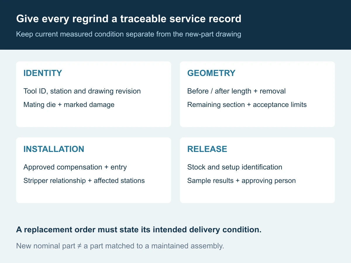
The following is a recommended control record, not a claim that every field requires the same measurement method. Assign responsibility before the tool leaves for service, especially when the component supplier cannot inspect the complete assembly.
| Record | Minimum useful detail | Decision it supports |
|---|---|---|
| Identity and condition | Tool ID, drawing revision, station, mating die ID and marked damage | Whether the correct component and failure are being addressed |
| Before / after geometry | Measured lengths, removal, remaining working section and applicable limits | Whether another service interval is geometrically permissible |
| Finished condition | Face form, cutting profile, edge condition and any required damage checks | Whether the serviced component meets its acceptance criteria |
| Assembly changes | Approved compensation, penetration, stripper relationship and affected station checks | Whether installation restores the intended working relationships |
| Production release | Stock identity and thickness, setup reference, sample results and approving person | Whether the sampled output meets the agreed requirements |
For the trial, agree which hole or blank dimensions, burr locations and other part characteristics matter, how they will be measured and how samples will be identified. Avoid “first part looks good” as the only evidence. Where early-run behavior is important, define an appropriate follow-up sample window for the process; there is no universal stroke count that proves future tool life.
6. Make the regrind-versus-replacement quotation comparable
A low regrinding charge can be misleading if it excludes condition assessment, installation work or the risk that inspection will reject the tool after transport. Ask for the scope and disposition, not a promised number of additional strokes.
- Regrind candidate: restorable wear, known dimensional margin and an approved route back to the working setup.
- Engineering hold: uncertain damage, missing minimum dimensions, unknown mating condition or an unapproved compensation proposal.
- Replacement candidate: consumed functional geometry, damage that cannot be accepted, or no approved way to restore the assembly within its limits.
For repeat purchasing, request the intended delivery condition explicitly: a new nominal component, a replacement matched to the current maintained assembly, or a component supplied with stated fitting allowance. These are different orders even when they share the same historical part number. A new full-length punch fitted into an assembly that still contains old compensation can produce the wrong entry.
Huicheng supplies custom stamping die components to agreed drawings and can help customers prepare drawings when the available information is incomplete. Send the component and assembly information together: existing drawings, relevant mating dimensions, current measured lengths, maintenance history, stock specification and part acceptance requirements. Any proposed regrinding, coating, assembly or trial work should be confirmed as part of the project scope rather than assumed to be included.
The buying insight: purchase a defined working condition, not simply a sharp edge. Recording what changed makes both the next maintenance decision and the next replacement order more reliable.
Frequently asked questions
How many times can a stamping punch be reground?
There is no universal count. Use measured removal and remaining functional dimensions against the approved limits for that punch and assembly. One deep regrind may consume more allowance than several light touch-ups.
Does sharpening change punch-to-die clearance?
Pure face grinding on an ideal, constant-section punch and parallel-land die need not change lateral clearance. Actual worn, tapered or relieved geometry can behave differently. Measure the resulting cutting profile and mating opening where the design requires it; do not infer clearance from unchanged part numbers.
Can a shim recover all lost grind life?
No. Approved compensation can restore position within its design limits. It cannot restore removed cutting land, working-section length, material integrity or the original coated face.
Can a replacement be made from a used sample?
A sample is useful evidence, but wear and previous compensation can obscure the intended dimensions. Identify those uncertainties and approve a replacement drawing before manufacture.
References and scope notes
- Dayton Lamina — Problem Solving Guide. Supports the distinction between edge damage and setup-related causes; individual remedies require application review. ↩
- Mate — Murata Wiedemann Tooling Catalog, maintenance and grind-life tables. Printed pages 43–44 illustrate tooling-specific limits; the 2021 catalog values are not specifications for a different tool. ↩
- UniPunch — Sharpening. Discusses maintaining die height after sharpening in its tooling context. ↩
- Mate — Punch & Die Maintenance. Guidance on sharpening condition and the limits of removing a visibly burned surface. ↩
The entry arithmetic, purchasing checklist and release-record structure are editorial engineering synthesis. The illustrations are original explanatory diagrams, not tooling drawings, measured test results or a substitute for machine-specific instructions.