Slug pulling occurs when a separated piece of material follows the punch back out of the die during withdrawal instead of remaining below the cutting zone. Replacing the punch may restore a damaged cutting edge, but it will not necessarily correct the mechanism that brought the slug back.
For a tooling buyer, the important distinction is between replacing a damaged component and preventing the next damage event. A punch can be the visible casualty without being the original cause. This guide focuses on piercing operations where the removed slug is scrap; when the separated piece is the intended product, its handling requirements must be defined differently.
Approve the cut edge and the scrap path separately. A dimensionally acceptable hole does not prove that the slug has cleared the tool safely for the next stroke.
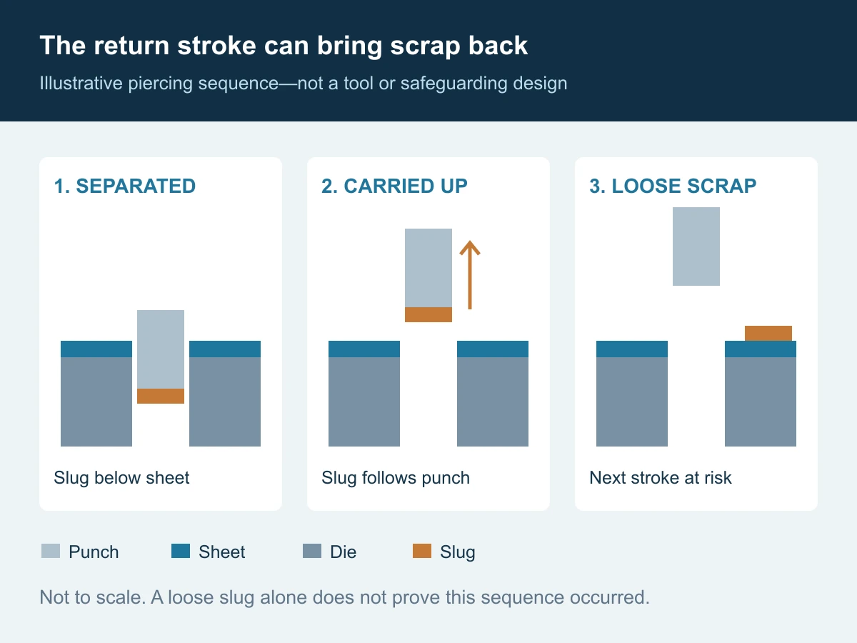
First establish whether the slug was pulled up or blocked below
A loose slug found on a strip is an observation, not a complete diagnosis. Before ordering a replacement, reconstruct where the scrap was first seen, what moved with it, and whether the event followed a maintenance or process change.
| Observed event | Working classification | Question to resolve |
|---|---|---|
| The separated slug visibly travels upward with the punch | Slug pulling or carry-up | What keeps it attached, and what should hold it below? |
| Scrap accumulates inside the die opening or downstream passage | Blockage or stacking | Where does forward scrap movement stop? |
| Scrap initially leaves the cutting zone but subsequently returns | Re-entry or rebound; confirm the path | What surface or handling condition returns it? |
| The strip rises with the punch while the scrap path is unclear | Strip-lifting or stripping problem; not yet proof of slug pulling | Is the strip being controlled as intended? |
These categories are a diagnostic framework, not mutually exclusive failure modes. A blocked passage and intermittent carry-up can coexist. Label uncertain events as uncertain rather than turning a mark on a part into proof of a particular mechanism.
Safety boundary: collect operating observations only through approved guarded monitoring arrangements. Inspection, clearing scrap and tooling adjustments require the site’s authorized isolation, stored-energy control and press-blocking procedures. Do not reach into a cycling press or defeat an interlock to obtain a better view.
A new cutting edge does not remove every attachment mechanism
CONIC’s tooling guidance identifies vacuum effects, oil-film adhesion, magnetic attraction and burr-related attachment as possible contributors to slug pulling.[1] These are different hypotheses. A photograph of a shiny new punch does not eliminate them, and residual magnetism is relevant only where the materials can respond to it.
Use that distinction to organize the evidence. If the event begins after sharpening, request the maintenance record and the resulting installed geometry. If it follows a lubricant change, record the actual product and application conditions. If it occurs at one station only, preserve that station’s identity rather than pooling all rejected parts into one sample bag.
The opposing side of the problem is retention in the die. In a published experiment on 1 mm CuSn6 sheet, researchers at the Technical University of Munich found that clearance, punch-edge radius and lubrication affected friction between the slug and the die after separation. Their results connect retention to the actual cutting conditions, not just the nominal hole size.[2]
This is useful evidence of interaction, not a transferable clearance chart. It does not justify deliberately dulling an edge or changing lubrication without reviewing the required part quality and process. A result obtained for one sheet material and test geometry is not a universal setting for connector tooling.
Our purchasing interpretation is straightforward: ask what changed in the complete station before assuming the replacement part needs a harder steel. Hardness, retention and scrap transport answer different questions.
Why “increase punch penetration” is not a universal answer
Punch entry should be reviewed against the specific tool design. Dayton warns that excessive entry can increase withdrawal vacuum and contribute to slug pulling. CONIC, in its own turret-tool guidance, describes sufficient entry as a way to push the slug into the intended lower-tool region. These recommendations address different configurations and should not be merged into a universal depth rule.[3]
The right supplier question is therefore not “How much deeper should we go?” It is: “At the approved installed position, where is the separated slug relative to the intended retention and relief geometry?”
That question calls for a section view showing the punch, die cutting region, relevant internal features and available travel. Include the current component lengths and any maintenance-related adjustments. Do not infer the installed relationship from an old nominal punch length alone.
For a replacement order, identify whether the customer expects an interchangeable part at the existing setup or a coordinated change to the station. Those are different scopes. Neither increasing entry nor removing material from the die should be treated as an informal receiving adjustment.
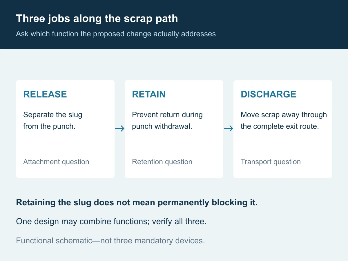
Release, retention and discharge are three separate jobs
A useful review follows the scrap from separation to collection:
- Release from the punch: what prevents the separated slug from continuing to travel with the punch face?
- Retention below the cutting zone: what prevents the slug returning during withdrawal?
- Discharge away from the tool: where does the scrap go after that controlled stage?
Dayton’s Slug Control system is an example of a die-side retention approach: engineered internal features create interference with the slug, followed by passage through the relief.[4] This illustrates a mechanism, not a claim that Huicheng supplies that branded system or that its geometry should be copied into another die.
Retention is not the same as permanent obstruction. When assessing a proposed retention feature, ask how the scrap subsequently advances through the complete passage. When assessing an ejector or an engineered air/vacuum arrangement, ask which part of the path it addresses. Detaching a slug is not, by itself, evidence of where it ends up.
A useful acceptance review asks for the route through the die insert, supporting components and downstream collection arrangement. A drawing that ends at the underside of the insert may leave the actual obstruction outside the purchased component’s scope.
Should you replace the punch, the die insert or both?
Separate two decisions on the purchase request: what is unfit for continued service and what change is intended to prevent recurrence. A damaged punch may need replacement even while the underlying cause is still being investigated. That does not make the replacement an established corrective action.
- Punch replacement: appropriate when its agreed acceptance characteristics are no longer met. Ask whether the original geometry remains suitable or an approved revision is needed.
- Die-insert replacement or revision: relevant when the cutting region, internal geometry or mating condition requires correction. Identify the dimensions and interfaces actually affected.
- Coordinated pair or station change: consider when changing one component alters the relationship that the other must satisfy. Include the relevant support and scrap-passage interfaces.
- No component change yet: reasonable when evidence points to an unresolved setup, lubrication, stripping or downstream handling issue. Purchasing new steel need not be the first experiment.
A supplier should be able to state which decision its quotation addresses. “New punch to existing drawing” and “revised tooling intended to improve slug control” should not carry the same acceptance language.
Consider a hypothetical sequence: a punch chips, a matching replacement is installed, acceptable holes appear briefly, and the same station fails again. This does not prove the replacement was defective. Our recommended response is to preserve the chronology and investigate the scrap event before changing the material specification. The sequence is illustrative, not a reported Huicheng customer case.
Send evidence the supplier can use, not only a broken punch
A sample can help document damage, but it cannot reveal all of the installed relationships. For a slug-pulling review, send a compact package with these five groups:
- Component definition: controlled punch and die drawings or models, revision, material condition, mounting references and relevant mating dimensions.
- Cutting task: sheet grade, temper or condition, actual thickness range, coating if applicable, pierced profile and specified clearance with its per-side or total convention.
- Installed configuration: section through the station, entry relationship, stripping arrangement, internal scrap route and any existing retention/ejection provision.
- Event record: station number, operating conditions when observed, last maintenance or material/lubricant change, tagged slug/part samples and safely obtained images.
- Requested deliverable: like-for-like component, drawing assistance, revised component proposal or a broader review; identify who approves changes and verifies the production result.
Huicheng can manufacture to customer drawings and help customers prepare drawings. If only an existing part or incomplete information is available, agree what additional measurements and mating details are needed. Drawing preparation should produce an approved specification, not silently turn wear damage into the new nominal geometry.
For Huicheng’s custom stamping punches, die inserts and stripper components, define whether the order covers the component alone or coordinated tooling work. Specialized slug-control features and any associated testing should be reviewed and quoted for the actual application; they are not assumed standard inclusions.
What evidence is enough to close the issue?
Use a validation plan agreed before the change. It should address the specific event and the final product requirements, rather than merely recording that a new component was installed.
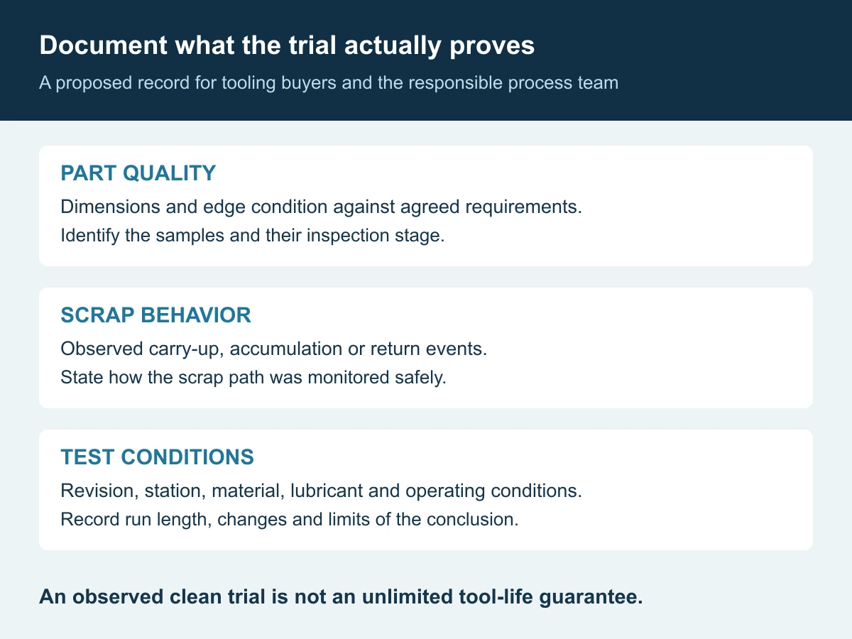
Record the drawing revision, affected station, material lot, lubricant condition, relevant operating settings, observation method and run length. State the required part dimensions and edge condition, the scrap behavior being checked and who can authorize production release. Stop and investigate abnormal events under the site’s approved procedures.
There is no universal number of trial strokes in this guide. A short demonstration may establish basic operation without representing the conditions under which an intermittent event previously occurred. Report the actual evidence—for example, no observed carry-up during the stated test—rather than converting it into an unlimited “slug-free” or tool-life guarantee.
If several variables are changed together, the trial may show that the revised combination works, but it cannot isolate which change caused the improvement. Where practical and safe, a controlled comparison gives more useful information for future maintenance and repeat orders.
The most useful closeout is a traceable explanation: the observed failure path, the approved change, the conditions checked and any remaining limits. That record is more valuable on the next reorder than an unexplained note saying “use the new punch.”
Frequently asked questions
Does slug pulling always mean the clearance is too large?
No. Clearance is one interaction in the system. Attachment, retention, installed geometry and scrap handling need to be distinguished before selecting a correction. Do not change a working cut-edge specification solely because a loose slug was found.
Should we remove lubricant to stop the slug sticking?
Not as a blanket remedy. Record and review lubricant conditions with the responsible tooling/process team. A change must remain compatible with the cutting operation and required part quality; this guide does not prescribe dry running.
Will an anti-slug feature guarantee trouble-free production?
No general guarantee follows from the feature name. Confirm the design’s application limits, installed relationship, discharge route and agreed validation evidence. Supplier-specific claims apply only to their stated products and conditions.
Can a new punch still be necessary if it was not the root cause?
Yes. Replacing damage restores a required component; controlling recurrence addresses the failure mechanism. Keep both tasks visible in the purchase and maintenance records.
References and scope notes
These primary sources support the technical principles identified in the text. They are not Huicheng product endorsements, universal setup instructions or company-specific performance guarantees. Diagnostic tables, RFQ requirements and validation recommendations are editorial guidance.
- CONIC: Countermeasures for Slug Pulling in Punching Process, Technical Information Vol. 1 — attachment mechanisms and examples for its NC turret tooling; its settings and lubrication suggestions are not universalized here. ↩
- Stahl et al. (2021): The Frictional Force between Slug and Die in Shear Cutting after Material Separation — TUM research abstract, CuSn6 test conditions and retention-force interactions; Key Engineering Materials 883, pp. 285–293, DOI 10.4028/www.scientific.net/KEM.883.285. ↩
- Dayton Lamina: Improving Perforating Die Performance — withdrawal, overentry and vacuum considerations; compared with the configuration-specific approach in reference 1. ↩
- Dayton Lamina: Dayton Slug Control System — an example of engineered die-side retention and subsequent relief; branded guarantees and geometry are not generalized. ↩