Precision does not mean applying the smallest possible tolerance to every dimension. A sound mold-component drawing concentrates control on the features that establish fit, motion, sealing, molded geometry and interchangeability. It also defines datums and an inspection method so that designer, supplier and buyer evaluate the same requirement.
Start with the assembly interface and failure mode. Control the relationship that protects function, select a feasible process, then define how conformity will be measured.
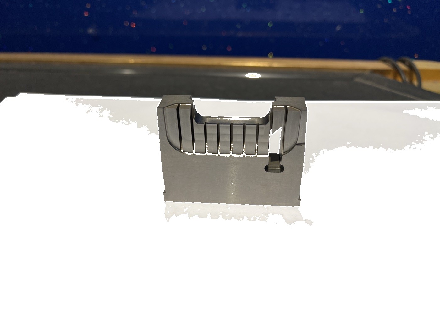
What does “match tolerance to function” mean?
It means the acceptance requirement is derived from what the feature must do in the mold. For example:
- a seating face controls support and installed height;
- a locating diameter or side face controls position;
- a shut-off controls sealing and flash;
- a slider interface controls motion and clearance;
- a forming surface controls molded-part geometry or appearance;
- a non-contact relief surface may only need adequate clearance.
ASME Y14.5 describes GD&T as a system for communicating design intent, fit, function and interchangeability.[1] ISO 1101 provides the symbol language and interpretation rules for form, orientation, location and run-out tolerances.[2] Neither replaces engineering judgment: the designer still has to identify the functional relationship.
Why does over-tolerancing increase cost and risk?
A tighter tolerance can change the process route, number of setups, finishing method, environmental control, inspection time and scrap risk. It may require grinding instead of milling, separate roughing and finishing electrodes, slower wire-EDM passes or more extensive CMM work. If that control does not protect function, the added work does not improve the mold.
| Drawing choice | Likely consequence | Better question |
|---|---|---|
| One tight ± tolerance everywhere | Cost without clear assembly protection | Which interfaces actually drive failure? |
| Coordinate dimensions from unrelated origins | Tolerance stack and ambiguous inspection alignment | What datum frame represents installation? |
| “Polish” without a measurable result | Different interpretations of finish and stock removal | What surface parameter or reference controls? |
| Tolerance near measurement capability | Supplier/customer pass-fail disputes | What method and decision rule will be used? |
How should functional interfaces be classified?
Before assigning numbers, mark each surface by function:
- Primary support. The face that seats the component and carries load.
- Location. Diameters, sides, keys or pins that control translation and rotation.
- Forming geometry. Surfaces that shape the molded or stamped product.
- Motion. Sliding, guiding, ejecting or cam-driven interfaces.
- Seal-off. Shut-offs and parting conditions that control flash or leakage.
- Clearance. Non-contact regions that only need to avoid interference.
This classification lets the drawing use profile, position, flatness, perpendicularity, size or surface texture where each communicates the real requirement. It also helps the supplier choose among CNC, grinding and EDM or wire EDM.
How should datums be selected for a mold component?
A datum reference frame should represent how the component is constrained when installed or functionally inspected. ISO 5459 defines the terminology and methodology for datums and datum systems.[3] The most convenient machining surface is not automatically the right primary datum.
Ask these questions:
- Which surface seats first and removes the most movement?
- Which feature locates the part laterally?
- What prevents rotation or fixes the final axial position?
- Can the inspection fixture simulate those constraints?
- Will heat treatment or finishing alter a datum before later operations?
A supplier may use process datums for intermediate operations, but final inspection should report the component in the drawing’s functional datum system. Otherwise, manufacturing and acceptance can describe different coordinate frames.
When should profile or position replace simple ± dimensions?
Simple coordinate dimensions can be clear for some sizes and distances. They become less effective when function depends on a feature’s relationship to a datum frame or when a complex surface must stay inside a defined zone. Position can control the location of holes, pins or features of size. Profile can control a line or surface relative to datums and is often useful for complex forming geometry.
This is not a rule to convert every drawing to GD&T. Use the control that most directly communicates the functional tolerance zone and can be manufactured and verified without ambiguity.
How do material and heat treatment affect achievable tolerance?
Material grade, initial condition, heat treatment, section thickness and interrupted geometry can all influence movement. A dimension that is easy to hold in annealed stock may require stock allowance, datum recovery and grinding after hardening. Thin walls or unbalanced stock removal can also change the plan.
For custom precision mold components, review the complete route before finalizing the tolerance. Where the route may include spark erosion, the EDM process-selection guide identifies the feature-access, electrode and surface questions to resolve:
- rough machining and stress balance;
- heat treatment and expected correction allowance;
- datum restoration;
- hard milling, grinding, sinker EDM or wire EDM;
- polishing, texturing or coating;
- final inspection after all dimension-changing operations.
Why must the measurement plan be agreed in advance?
A tolerance is incomplete as a commercial acceptance rule when the parties apply materially different measurement methods. NIST’s work on coordinate metrology identifies effects from machine geometry, probes, software, fixturing, thermal conditions and the measurement task.[4] ISO 14253-1 addresses how measurement uncertainty is considered in conformity decisions near specification limits.[5]
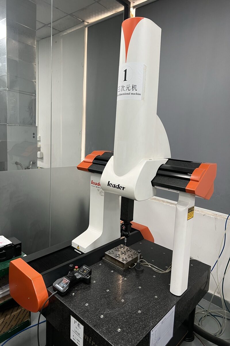
For every critical characteristic, agree on:
- datum alignment and fixture condition;
- instrument or functional gauge;
- point density or scanning strategy;
- filter and evaluation method where relevant;
- temperature conditioning;
- report format and rounding;
- decision rule for a result close to the limit.
ISO 1:2022 defines the standard reference temperature for geometrical and dimensional properties.[6] A temperature-controlled room helps, but the component and measurement system also need suitable stabilization for the task.
A five-step functional tolerance review
- Name the failure mode. Interference, flash, leakage, mismatch, drag, poor molded dimension or loss of interchangeability?
- Identify the controlling relationship. Which two or more features protect against that failure?
- Choose functional datums. Reproduce the installed constraint sequence.
- Check manufacturing feasibility. Confirm process, material, heat treatment and finishing route.
- Define verification. Ensure the tolerance can be measured with adequate confidence and reported consistently.
Record those decisions in the sourcing package so they survive handoffs between design, purchasing and inspection. The precision mold component RFQ guide provides a supplier-ready checklist.
Frequently asked questions
Does a smaller tolerance always produce a better mold component?
No. A smaller tolerance is valuable only when it protects function and can be verified meaningfully. Unnecessary tightness can add cost, lead time and rejection risk.
Should general tolerances apply to critical interfaces?
Critical interfaces should normally be identified individually with the control that reflects their function. General tolerances remain useful for non-critical dimensions within their intended scope.
Can manufacturing capability replace a drawing tolerance?
No. Process capability informs a feasible design, but the drawing or controlled product definition states what is accepted. Confirm feature-specific capability instead of applying one machine accuracy number to the entire part.
Need a tolerance and process review before release? Send the controlled drawing, 3D model, material, hardness and mating information through Huicheng’s contact page. We can review functional interfaces, process route and inspection requirements with the RFQ.