A replacement mold insert can pass every dimension on its own drawing and still fail in the mold. The reason is usually not a single “bad” dimension. It is a broken chain between the mold interface, the datum system, the manufacturing route and the inspection setup.
This guide explains how mold owners, maintenance teams and sourcing engineers can specify a replacement insert so that the supplier is solving the actual assembly problem—not merely copying a loose component. It is written for cavity and core inserts, shut-off inserts, connector-mold details and other drawing-specific precision mold inserts.
Define the interfaces first, establish datums from how the insert sits and locates in the mold, separate nominal geometry from intentional fitting stock, and agree on the inspection method before steel is cut.
Why “copy the old insert” is an incomplete instruction
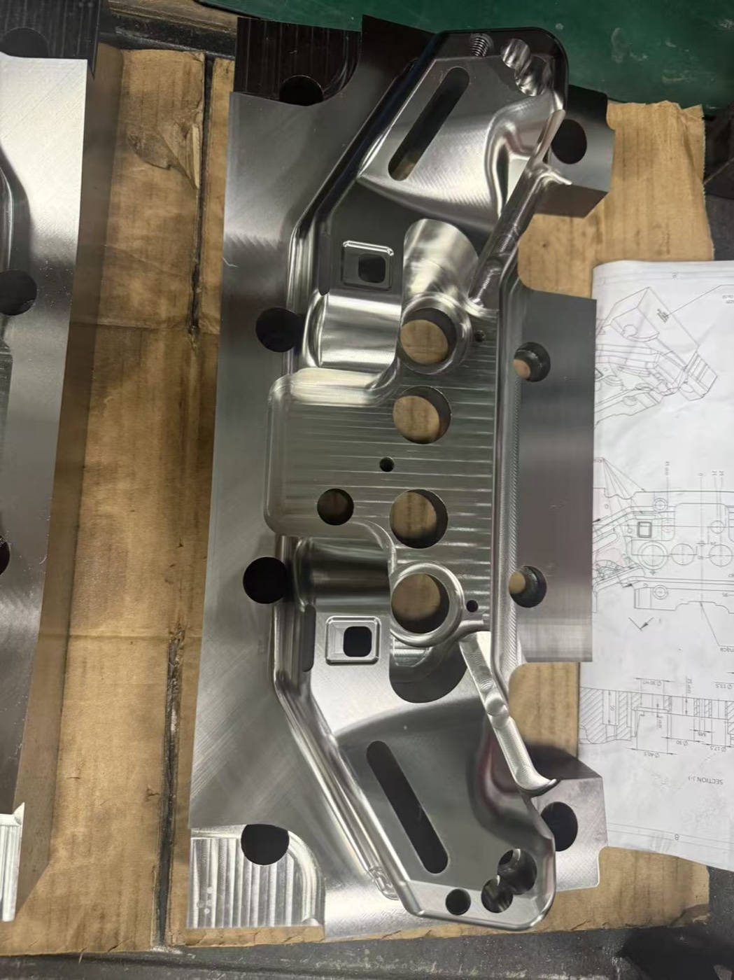
An old insert contains useful evidence, but it is not automatically the design authority. It may be worn, polished, repaired, intentionally hand-fitted, thermally distorted or made to an earlier revision. Reverse-engineering every measured value can reproduce those conditions—including the ones you are trying to remove.
Before asking a supplier to copy the part, classify the available data:
- Nominal design: the released 2D drawing and 3D model, including revision and applicable GD&T standard.
- Actual insert: measurements from the component being replaced, with worn or damaged areas identified.
- Actual mold interface: the pocket, keys, screws, support faces, shut-offs, adjoining inserts and cooling or sealing features that constrain the replacement.
- Molded-part evidence: flash, mismatch, drag, short shots, dimensional drift or cosmetic defects connected to the area.
- Intentional deviations: fitting stock, process compensation or repairs that were approved after the original mold trial.
When these disagree, the customer should identify which condition governs. If that decision cannot be made immediately, the supplier can report the conflict before quotation or propose a safe intermediate condition for approval. Silent averaging is not a control plan.
Start with five interfaces—not a list of dimensions
Mark the insert drawing by function. A useful review separates five kinds of interface because each one creates a different failure mode and may require a different process or measurement method.
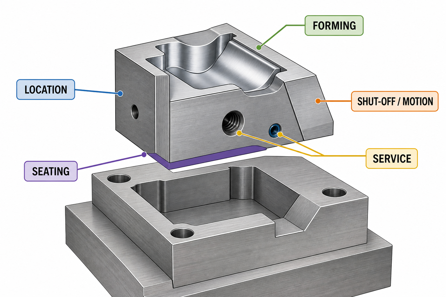
| Interface | What it controls | Typical release risk | Evidence to request |
|---|---|---|---|
| Seating | Support and installed height | Rocking, local loading, proud or low insert | Flatness, parallelism and contact check |
| Location | X-Y position and rotation | Parting-line or feature mismatch | Position/profile to functional datums |
| Forming | Molded geometry and finish | Wrong product size, texture break or witness line | Profile data, finish requirement and molded-part check |
| Shut-off / motion | Seal-off and moving clearance | Flash, galling, drag or collision | Angle, contact pattern and movement check |
| Service | Fastening, cooling, venting or sealing | Leakage, blocked vent, screw conflict | Thread/port details and leak or flow test if applicable |
This interface map also prevents “tight tolerance everywhere.” A locating face may deserve stronger control than a non-contact clearance surface. A cosmetic forming surface may require profile and finish control even when its overall size is not the tightest dimension. Precision should follow function; the related guide to matching mold-component tolerance to function explains how to rank those requirements.
Build the datum system from the installed condition
A datum reference frame is not simply the three easiest surfaces to probe. It should represent how the insert is constrained when installed. ASME Y14.5 describes GD&T as a language for communicating design intent, fit, function and interchangeability.[1] ISO 5459 likewise provides the terminology and rules for datums and datum systems in technical product documentation.[2]
For a typical rectangular insert, the primary datum may be the broad seating face, the secondary datum a locating side, and the tertiary datum an end face or key feature. But this is only an example. A round insert may locate from a diameter and flange face; a keyed component may need the key to control rotation. The correct order depends on the real constraint sequence.
Ask four questions during drawing review:
- Which feature first contacts the mold and removes the most degrees of freedom?
- Which feature locates the insert laterally?
- What prevents rotation or sets the final axial position?
- Can inspection physically simulate those constraints without distorting the part?
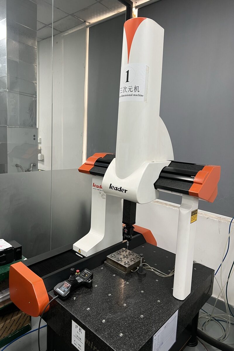
If the manufacturing setup, CMM alignment and assembly condition each use unrelated origins, three internally consistent results can still describe three different parts. The supplier should translate the design datum system into process datums where necessary, then return final acceptance results to the drawing datums.
Decide what is finished, what is fitted and what is left for trial
“Make to nominal” and “leave stock” are both ambiguous unless they name the feature, amount, direction and release step. A safer fitting-stock instruction states:
- the exact surface or balloon number;
- stock per side or total stock;
- whether the allowance is on steel, molded-part geometry or a shut-off;
- who removes it and at which stage;
- the measurement or trial evidence needed before final finishing.
This matters most on shut-offs, parting-line details, texture-matching surfaces and geometry affected by molding compensation. If all fitting stock is removed before the actual mold condition is known, there is no controlled way to put steel back. If excessive stock is left without a fitting plan, assembly time simply moves downstream.
Freeze the process route before the critical features are finished
The route should follow material, hardness, geometry, distortion risk and the interfaces above. It may combine CNC, heat treatment, grinding, wire EDM and sinker EDM. Huicheng’s EDM and wire EDM capability is used where access, hardness or feature geometry justifies it—not as an automatic substitute for a process plan. For feature-level selection, see when EDM is the right process for a mold insert.
A practical route review identifies:
- Material identity and condition. Confirm grade, supplier designation, hardness range and any required certificate before cutting.
- Heat-treatment position. Decide which stock remains for correction after hardening and which delicate features should be finished later.
- Datum preservation. Protect or re-establish the surfaces needed to relocate the part after heat treatment.
- Critical-feature sequence. Finish related locations in a coordinated setup where practical, especially when their relationship matters more than each isolated size.
- Surface integrity. Define polish direction, EDM finish, edge condition and any recast-layer or micro-crack requirement appropriate to the application.
A process capability statement such as “EDM accuracy 0.002 mm” should never be applied as a blanket promise to every feature. Final capability depends on part size, geometry, setup, electrode or wire strategy, thermal condition and the measurement task. Acceptance remains feature-specific.
Agree on the inspection method before machining
A report with many green cells is not useful if buyer and supplier are measuring different characteristics. ISO 1101 provides the symbol language and interpretation rules for geometrical tolerancing.[3] ISO 14253-1 addresses conformity decisions near specification limits and explicitly accounts for measurement uncertainty.[4] NIST’s work on CMM uncertainty also identifies influences from machine geometry, probes, software, fixturing and thermal conditions.[5]
For every critical-to-function characteristic, agree on:
- drawing balloon or feature ID;
- datum alignment and datum simulation;
- instrument and probing or scanning strategy;
- sampling density for profile, form or freeform surfaces;
- fixture and clamping condition;
- temperature conditioning and any compensation;
- the rule for results close to the tolerance limit;
- required output: numeric report, CMM graphic, scan comparison, material certificate or photos.
ISO 1:2022 defines the standard reference temperature used for geometrical and dimensional properties.[6] This does not mean every shop result is automatically equivalent because “the room has air conditioning.” The part and measuring system need adequate stabilization, and the agreed report should make the inspection condition clear when thermal effects are significant.
If a tolerance is only a few times larger than the expected measurement uncertainty, ask how conformity will be decided before production. Do not wait for one laboratory to say “pass” and another to say “fail.”
Use three release gates instead of one final inspection
A single final report discovers problems late. A replacement-insert project is easier to control with three explicit gates.
Gate 1 — design and risk release
Freeze the revision, applicable standard, functional datums, critical interfaces, material, hardness, fitting stock and open questions. If the old insert and released data disagree, document the chosen authority.
Gate 2 — steel-safe or pre-finish review
Check material and heat-treatment evidence, datum recovery, major geometry and the features that would be expensive or impossible to correct after final finishing. Review intentional stock on shut-offs and forming surfaces.
Gate 3 — fit, function and shipment release
Complete the balloon report, inspect critical profiles and interfaces, verify threads and service features, and perform an agreed bench fit or mold fit where access is available. Protect precision surfaces for shipment and keep the inspection revision with the part.
For new or modified tooling, dimensional acceptance is followed by functional evidence. Huicheng’s mold trial and injection molding service can support trial planning when a physical mold, resin and acceptance sample are part of the project scope. A mold trial should have defined parameters and acceptance criteria; “the mold ran” is not a complete result.
A supplier-ready replacement insert package
Send the following at RFQ stage whenever possible. If an item is unavailable, mark it as unavailable instead of leaving the supplier to guess.
- released 2D PDF and native 3D model, with matching revision;
- photo of the installed insert and its orientation in the mold;
- photos or scan data for wear, damage and repaired areas;
- mold-pocket and neighboring-component measurements when fit is in question;
- material, hardness, coating, polish, texture and edge requirements;
- marked seating, locating, forming, shut-off/motion and service interfaces;
- critical characteristics with the required inspection output;
- explicit fitting-stock instructions;
- molded-part defect photos and last approved sample, if available;
- target date, quantity, shipping destination and trial responsibility.
This package does more than improve quotation accuracy. It allows the supplier to challenge an impossible datum setup, identify an inaccessible measurement, reserve stock for a controlled fit and plan the manufacturing sequence before cost is locked in. Use it together with the broader precision mold component RFQ guide when material certification, revision control, delivery and commercial scope also need to be defined.
The acceptance question that prevents most disputes
Before placing the order, ask one question:
“What exact evidence will demonstrate that this insert will locate, seat, form, move and seal as intended in our mold?”
The answer should point to defined characteristics and checks—not simply “we will inspect it.” When the evidence chain is clear, machining, measurement and mold trial are all testing the same design intent.
Need a replacement insert review? Send the drawing, model, material, photos of the old component and any mold-interface measurements through Huicheng’s RFQ contact page. We can identify missing inputs, propose a process and inspection route, and confirm what should be resolved before manufacturing.
Frequently asked questions about replacement mold inserts
Can a replacement mold insert be manufactured from the old insert alone?
Sometimes, but an old insert should be treated as evidence rather than automatic design authority. Wear, polishing, repairs and previous hand fitting can change its geometry. A safer package combines the old component with the released drawing or model, mold-pocket measurements, defect evidence and a written decision about which condition governs.
How much fitting stock should be left on a replacement insert?
There is no universal allowance. The amount depends on the interface, material condition, process sequence, expected mold trial and who will complete the fitting. Specify the exact surface, the allowance per side or in total, the stock direction, the removal stage and the evidence required before final finishing.
What inspection report should accompany a replacement insert?
The report should identify the drawing revision, ballooned critical characteristics, datum alignment, measurement method and actual results. Depending on risk, it may also include a CMM graphic or scan comparison, material and hardness certificates, surface-finish evidence, thread or port checks, contact-pattern photos and an agreed bench-fit or mold-fit record.
References
- ASME Y14.5 — Dimensioning and Tolerancing.
- ISO 5459:2024 — Geometrical tolerancing: Datums and datum systems.
- ISO 1101:2017 — Geometrical tolerancing.
- ISO 14253-1:2017 — Decision rules for verifying conformity or nonconformity.
- NIST IR 5170 — Measurement uncertainty considerations for coordinate measuring machines.
- ISO 1:2022 — Standard reference temperature for geometrical and dimensional properties.