A mold-insert surface finish is not fully specified by writing “Ra 0.8” or “polish to mirror.” A usable requirement must identify the functional surface, the governing parameter and standard, the manufacturing condition in which it applies, the measurement method, and any defects that a roughness number cannot control.
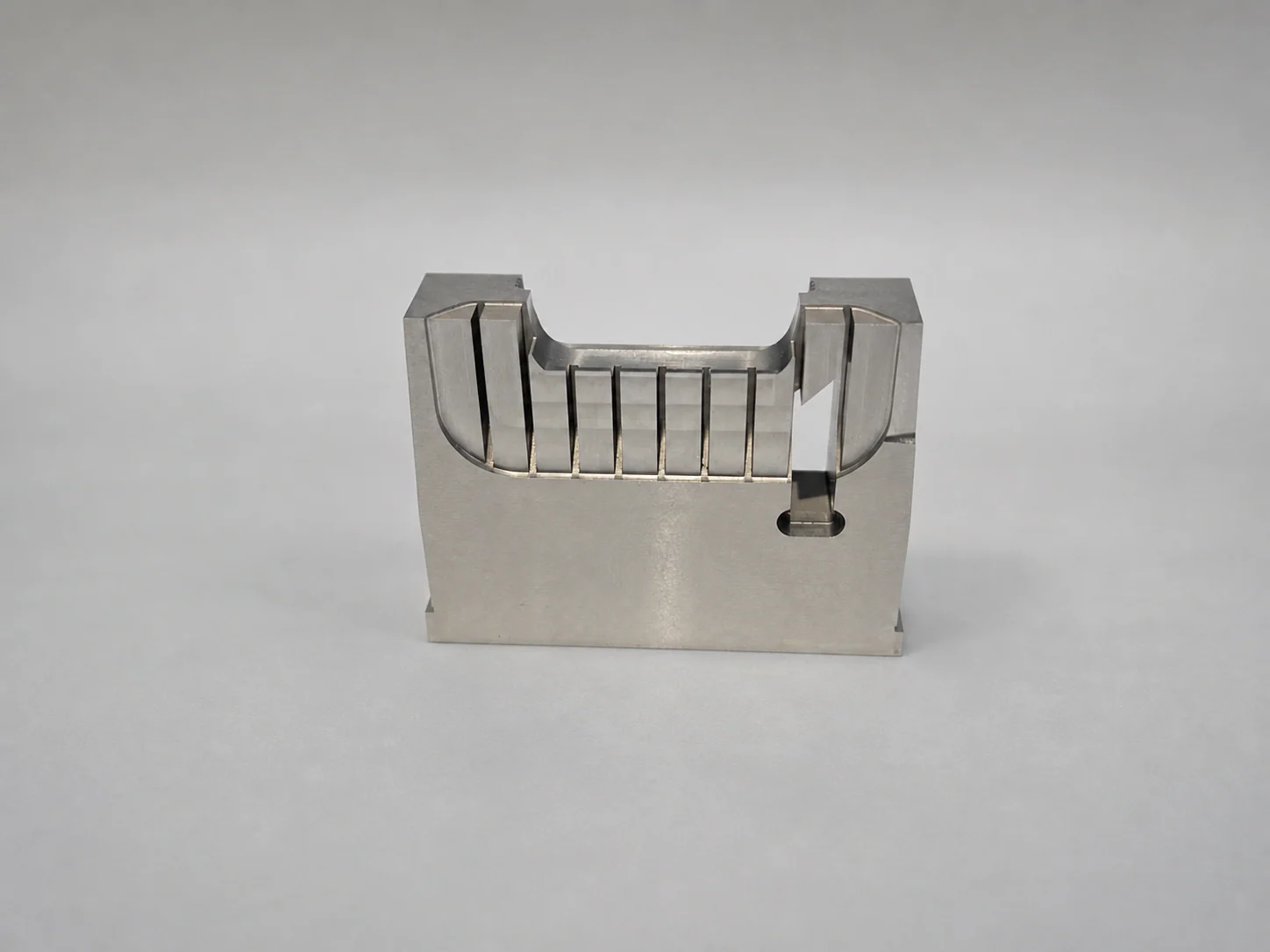
This guide gives mold designers, sourcing engineers and quality teams a practical way to connect surface function, machining route and acceptance evidence. It applies to cavity and core details, shut-offs, sliders, replacement inserts and other drawing-specific precision mold inserts.
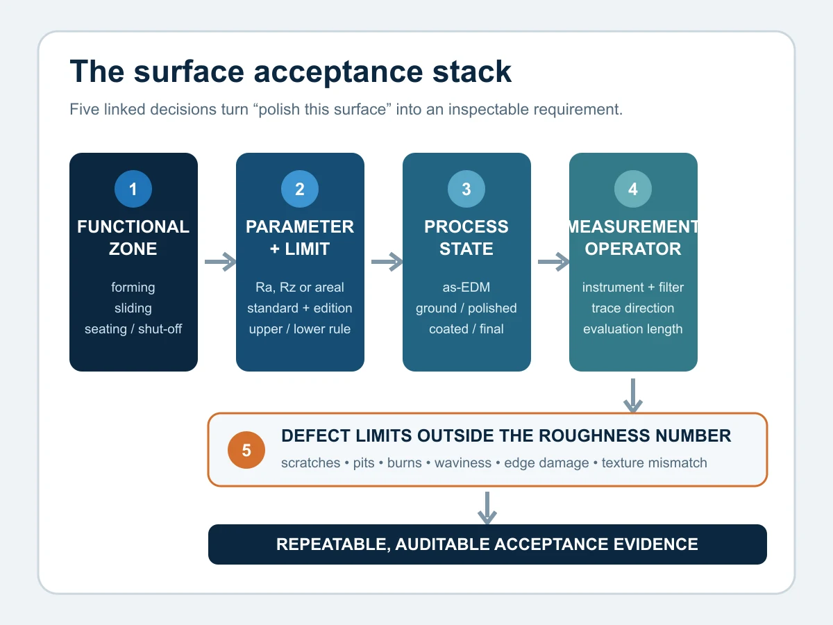
Specify surface finish as a five-part acceptance stack: functional zone + parameter and limit + process state + measurement operator + separate defect criteria. If one part is missing, two capable suppliers can make different surfaces and both believe they followed the drawing.
Why “Ra 0.8” is not a complete surface specification
Ra is useful because it summarizes average profile deviation in one value. But an average cannot describe every feature that affects molding or mold life. Two surfaces can have a similar Ra while differing in peak height, deep valleys, spacing, waviness, lay direction or isolated damage. A roughness result can therefore be numerically acceptable while a shut-off scratches, a slider retains poor lubrication, or a cosmetic surface shows an unwanted pattern.
ISO 21920-2 defines profile-method terms and surface-texture parameters, while ASME B46.1 covers roughness, waviness and lay.[1][4] The engineering lesson is simple: choose a parameter because it represents the functional risk—not because it is the default field in a drawing template.
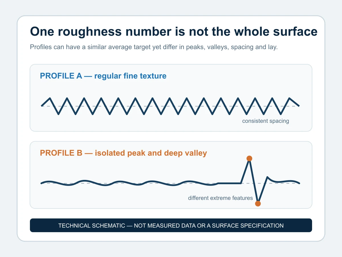
Ra and Rz are also not interchangeable labels for “smoothness.” Ra is an averaging parameter; Rz is more responsive to the profile’s vertical extremes. Their exact definitions and evaluation rules must come from the standard and edition named on the drawing. If the customer and supplier silently use different conventions, the numbers may look precise while the acceptance rule remains ambiguous.
A second problem is that roughness and surface imperfections are different control problems. ISO 8785 treats imperfections such as scratches, cracks and pores separately from ordinary texture parameters.[7] A no-scratch cosmetic requirement, an EDM-burn prohibition or an edge-break requirement should therefore be written explicitly; it should not be assumed to hide inside an Ra value.
Use a five-part surface acceptance stack
A reliable surface-finish callout answers five linked questions. This framework is more useful than starting with a polishing grade because it begins with design intent and ends with evidence.
1. Functional zone: where does the requirement apply?
Identify the exact face, patch, band or boundary. “All surfaces” is rarely a sensible instruction for a precision insert. A drawing should distinguish a molded cosmetic face from a mounting face, a vent land, a shut-off, a sliding surface and a non-contact clearance area. Use surface IDs, drawing balloons, hatched zones or a controlled CAD model so the boundary is unambiguous.
2. Parameter and limit: what characteristic is controlled?
Name the parameter, numerical limit, unit, acceptance direction and governing standard. ISO 21920-1 covers how profile surface texture is indicated in technical product documentation; ISO 21920-3 addresses the complete specification operator for profile methods.[2][3] If the contract follows ASME practice, name ASME B46.1 and the applicable edition instead.[4]
Do not mix a parameter from one system with an evaluation rule assumed from another. Also state whether a value is a maximum, minimum, range or another defined acceptance condition. The supplier should not have to infer which side of the number matters.
3. Process state: at what manufacturing stage does it apply?
A surface can be measured after EDM, after stoning, after polishing, after coating or in the final assembled condition. These are not equivalent. State the accepted condition and whether later processing may alter it. If stock is intentionally reserved for texture, fitting or final polish, identify the allowance and the release step.
4. Measurement operator: how will the value be produced?
Define enough of the measurement method that buyer and supplier can reproduce the result: profile or areal method, instrument type, filter and cutoff or nesting index, evaluation length, trace direction, location, number of traces and treatment of form. “Use a roughness tester” is not a complete plan.
5. Separate defect limits: what must not be present?
List visually or functionally unacceptable conditions that a roughness value may miss: scratches, pits, burns, chatter, ripples, drag marks, edge rollover, polish direction, local texture mismatch or damaged shut-off corners. Define the inspection method—visual standard, magnification, approved sample, replica or another agreed method—where those conditions are important.
Match surface finish to what the mold surface actually does
Surface finish should follow function in the same way that dimensional tolerance should. The related guide on matching mold-component tolerance to function explains why blanket precision creates cost without necessarily improving assembly. The table below applies that principle specifically to surfaces.
| Surface function | Primary risk | Specification focus | Acceptance evidence |
|---|---|---|---|
| Cosmetic forming face | Gloss, haze, read-through or visible texture break | Defined zone, approved appearance, polish/texture direction and prohibited defects | Measured texture plus visual standard or approved molded sample |
| Shut-off / parting interface | Flash, local loading, fretting or loss of contact | Geometry, contact condition, lay and edge integrity—not roughness alone | Dimensional result, contact evidence and edge inspection |
| Sliding / guiding face | Wear, galling, poor oil retention or stick-slip | Roughness family, lay direction, mating material and lubrication condition | Traces in the agreed direction plus fit or motion check where required |
| Seating / mounting face | Rocking, unstable installed height or concentrated load | Flatness, parallelism and burr control together with finish | Geometry report, surface check and contact check if critical |
| Vent land | Blocked gas path, flash or unstable venting | Depth, width, land length, edge and contamination; roughness is secondary | Section dimensions and clean visual inspection |
| Non-contact clearance face | Unnecessary cost or missed burrs | Economical process finish with explicit burr and contamination limits | Visual and basic dimensional verification |
This matrix prevents a common sourcing error: asking for the finest finish everywhere and then discovering that the real failure came from geometry, lay, an isolated scratch or an undefined mating condition. Surface texture is one layer of functional control, not a replacement for it.
Connect EDM, grinding and polishing to the final accepted state
The drawing does not need to dictate every shop operation, but it must protect design intent through the route. A typical insert may pass through milling, heat treatment, grinding, sinker EDM, wire EDM, stoning and polishing. Each step changes what remains available for correction.
After EDM
EDM is appropriate when access, hardness or internal geometry makes rotating-tool machining unreliable. It also leaves a process-specific surface. The required finish, number of trim passes, later stock removal and any surface-integrity requirement should be coordinated before the electrode or wire strategy is frozen. See the detailed guide on when EDM is the right process for a mold insert and Huicheng’s EDM and wire EDM capability.
Do not write an as-EDM roughness requirement if the acceptance measurement will occur after polishing. Conversely, do not measure the polished surface and treat that value as proof that the underlying EDM route met a separate surface-integrity requirement. Those are different questions.
After grinding
Grinding can generate a controlled surface and strong geometric relationships, but direction matters on sliding, sealing and cosmetic-transfer surfaces. The drawing or inspection plan should state the trace direction relative to the lay. Cross-lay and along-lay measurements can produce different results on the same surface.
After hand polishing
Polishing is not merely “making Ra smaller.” It can soften edges, alter small radii, round shut-offs, change local profile and create waves that a short trace misses. Protect critical geometry with stock rules, edge instructions and intermediate inspection. If appearance is the governing requirement, use an approved physical or molded reference together with measured texture; neither should silently substitute for the other.
Which surface condition is contractual: as-machined, as-EDM, after hand finishing, after coating, or final after mold fitting? Put that answer next to the finish requirement—not in an email that may be separated from the drawing.
Build an inspection plan that can reproduce the result
Profile measurement and areal measurement answer related but different questions. ISO 21920 covers profile surface texture; ISO 25178-2 defines parameters for areal methods.[1][5] A line trace can be efficient for accessible, directionally controlled surfaces. Areal topography can be more informative when texture is non-directional, localized or functionally dependent on a patch rather than one line. The choice should be risk-based and agreed before final finishing.
NIST’s surface-finish metrology work describes stylus and optical profiling methods and emphasizes that filtering, stylus geometry and measurement setup affect the reported profile.[8] ISO 12179:2026 addresses calibration and adjustment of contact stylus instruments using measurement standards.[6] A calibration sticker is necessary, but it does not resolve a wrong trace direction, unsuitable cutoff, inaccessible location or inconsistent data processing.
For each critical surface, record:
- location: exact zone and distance from edges, radii, gates or vents;
- direction: across, along or at a defined angle to the lay;
- method: contact stylus, optical profiler or another agreed technique;
- operator settings: filter, cutoff or nesting index, evaluation length and parameter definition;
- sampling: number of traces or measurement areas and the acceptance rule for the set;
- condition: cleaning, temperature stabilization, coating and final process state;
- instrument access: whether the probe can reach the real surface without collision or edge influence;
- reporting: actual values, trace or map where useful, equipment identification and measurement date.
Deep ribs, narrow slots and steep internal walls may be difficult or impossible to measure with a conventional stylus in the specified location. Treat access as an RFQ question. The buyer and supplier can move the inspection point, use an agreed replica method, select a suitable optical method, qualify a process coupon, or define process evidence—but the alternative must be approved before production, not invented after a failed final inspection.
Worked example: turn a vague note into an acceptance plan
Consider a cavity insert with a cosmetic forming face, a ground seating face and a narrow EDM rib. A vague drawing says:
“Polish mold surface to Ra 0.4. No EDM marks.”
The note leaves open at least seven questions: which surface, which standard, maximum or target value, measurement direction, evaluation setting, stage of measurement, and what “EDM marks” means. A supplier-ready release could separate the requirements:
- Zone F1 — cosmetic forming face: identify the profile or areal parameter, limit, standard edition, final polished condition, measurement locations and approved appearance reference. List scratches, pits and polish waves as separate visual defects.
- Zone S1 — seating face: specify finish together with flatness, parallelism, burr control and trace direction across the grinding lay.
- Zone E1 — narrow EDM rib: define the accepted final process condition, dimensional/profile requirement and the approved method for surface verification if normal stylus access is not possible.
The improved note is longer, but quotation becomes more reliable because the supplier can plan electrodes, finishing stock, inspection access and reporting. The customer also avoids paying cosmetic-polish cost on a non-visible mounting face.
Surface-finish checklist for an RFQ or controlled drawing
Add this checklist to the broader precision mold component RFQ package. For a worn component, also use the replacement mold insert datum, fit and inspection guide so surface evidence is not separated from the actual mold interface.
- Mark every critical surface zone and its boundary.
- State the governing surface-texture standard and edition.
- Name the parameter, limit, unit and acceptance direction.
- Define the final process state to which the requirement applies.
- Record polish direction, texture direction or prohibited lay where functional.
- Separate scratches, pits, burns, waviness, edge damage and appearance criteria from Ra/Rz.
- Define profile versus areal measurement and the inspection settings.
- Confirm trace direction, measurement locations and sampling quantity.
- Resolve instrument access for ribs, slots, radii and steep walls.
- Identify any stock left for texture, fitting, coating or mold trial.
- Provide an approved visual or molded sample when appearance governs.
- State the evidence required with shipment: values, traces, maps, photos or certificates.
Need a surface-finish review before quotation? Send the drawing, 3D model, material/hardness, molded-part appearance requirement and the surfaces that are critical through Huicheng’s RFQ contact page. We can flag ambiguous zones, process-state conflicts and measurement-access problems before machining begins.
Frequently asked questions
Is Ra alone enough to specify a mold-insert surface?
Usually not for a critical surface. Ra does not by itself define Rz, lay, waviness, isolated scratches, pits, appearance or the measurement operator. At minimum, identify the surface zone, governing standard, limit, final process state and measurement conditions. Add separate defect or appearance criteria when they affect function.
Can two surfaces with the same Ra perform differently?
Yes. They can differ in peak and valley structure, spacing, lay, waviness and isolated defects. These differences can affect sliding, contact, release and visible molded appearance. Select parameters and evidence from the surface’s functional risk rather than treating Ra as a universal quality score.
Should an EDM surface be measured before or after polishing?
Measure the condition named by the requirement. If final acceptance is after polishing, the report should describe the polished state. If the design also controls the as-EDM condition or surface integrity, treat that as a separate requirement with its own evidence. Do not use one result as proof of both.
When should areal measurement be used instead of a stylus trace?
Areal measurement can help when a local patch, non-directional texture or complex topography is functionally important. A profile trace can be efficient for accessible surfaces with a defined lay and trace direction. Choose the method before final finishing and ensure both parties use compatible definitions and settings.
Can a standard CMM report replace a surface-roughness report?
Not automatically. A CMM is excellent for geometry, but ordinary probing does not necessarily have the tip geometry, sampling density, filtering or validated method required for surface texture. Use a qualified surface-measurement method unless a specific CMM-based method has been demonstrated and agreed for the requirement.
What should a supplier report for a critical polished surface?
Report the drawing revision, surface-zone ID, final process condition, parameter and actual result, instrument/method, measurement location and direction, operator settings required by the specification, and separate visual-defect evidence. For cosmetic molding, include the agreed appearance or molded-sample comparison.
References
- ISO 21920-2:2021 — Surface texture: Profile — Terms, definitions and surface texture parameters.
- ISO 21920-1:2021 — Surface texture: Profile — Indication of surface texture.
- ISO 21920-3:2021 — Surface texture: Profile — Specification operators.
- ASME B46.1-2019 (R2026) — Surface Texture (Surface Roughness, Waviness, and Lay).
- ISO 25178-2:2021 — Surface texture: Areal — Terms, definitions and surface texture parameters.
- ISO 12179:2026 — Calibration of contact (stylus) instruments.
- ISO 8785:1998 — Surface imperfections — Terms, definitions and parameters.
- NIST — Introduction to Surface Finish Metrology.