A CMM report does not prove a precision mold insert is conforming unless the measurement reproduces the drawing’s datum logic and states how the result was acquired and accepted. Machine accuracy matters, but so do alignment, stylus access, point distribution, software evaluation, temperature, task-specific uncertainty and the decision rule used near a tolerance limit.
This buyer-focused guide explains how to specify and review CMM inspection for mold inserts. It is intended for tooling engineers, quality teams and purchasing teams that need evidence they can use—not a page of green check marks with no defensible connection to the drawing.
Define the datum reference frame first, then agree which features are accessible, how complex surfaces will be sampled, what uncertainty and decision rule apply, and which actual values must appear in the report. Use best-fit analysis for diagnosis only when it is explicitly separated from datum-based acceptance.
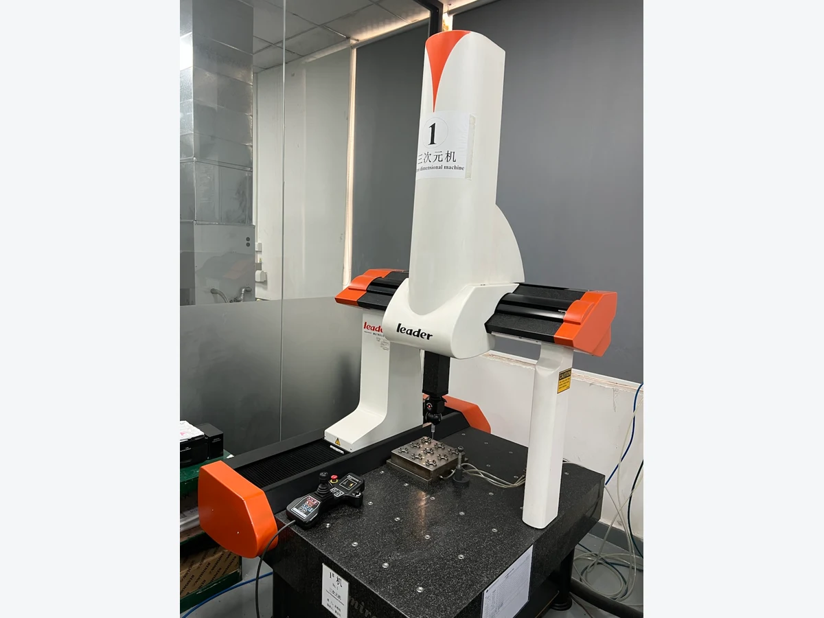
Why a CMM report can still be ambiguous
A coordinate measuring machine records points or scan data and uses software to construct features and calculate characteristics. That capability is powerful, but the output depends on choices made before and during the program. Two reports can use the same machine and the same workpiece yet produce different results if they use different alignments, point locations, filters, fitting algorithms or temperature assumptions.
ISO 5459:2024 provides the terminology and rules for datums and datum systems in geometrical product specification.[1] ISO 1101:2017 defines the symbol language and interpretation rules for form, orientation, location and run-out tolerances.[2] Together, those drawing requirements are the starting point. A CMM program should implement the specification; it should not silently invent a more convenient coordinate system.
For a useful report, the buyer needs to know at least:
- the drawing and CAD revisions used to create the program;
- the datum features, datum order and material-boundary conditions used for alignment;
- the probe, stylus, qualification status and reachable directions;
- the measurement strategy: discrete points, scanning paths, point density and excluded regions;
- the construction and evaluation rules used by the software;
- the part state, fixturing, cleanliness and thermal-conditioning conditions;
- the actual measured values, units and stated acceptance rule;
- the relevant measurement uncertainty or an agreed capability statement for the specific task.
This is why a generic “CMM inspected” note is not enough for a precision mold insert. The inspection plan must connect the result to the way the insert locates, seals, forms the part and interfaces with the mold.
Functional datum alignment versus best fit
A functional datum alignment constrains the measured data in the order defined by the drawing’s datum reference frame. In a common primary-secondary-tertiary scheme, the primary datum establishes the main orientation, the secondary datum removes further degrees of freedom, and the tertiary datum completes the location. The exact constraints depend on the defined datum features and modifiers—not on a universal 3-2-1 shortcut.
A best-fit alignment takes a different approach. It translates and/or rotates measured data to minimize a selected deviation criterion. That can be valuable for diagnosing process patterns, comparing freeform surfaces or visualizing how a deviation is distributed. But it can also redistribute or hide a real location or orientation error relative to the mold interfaces.
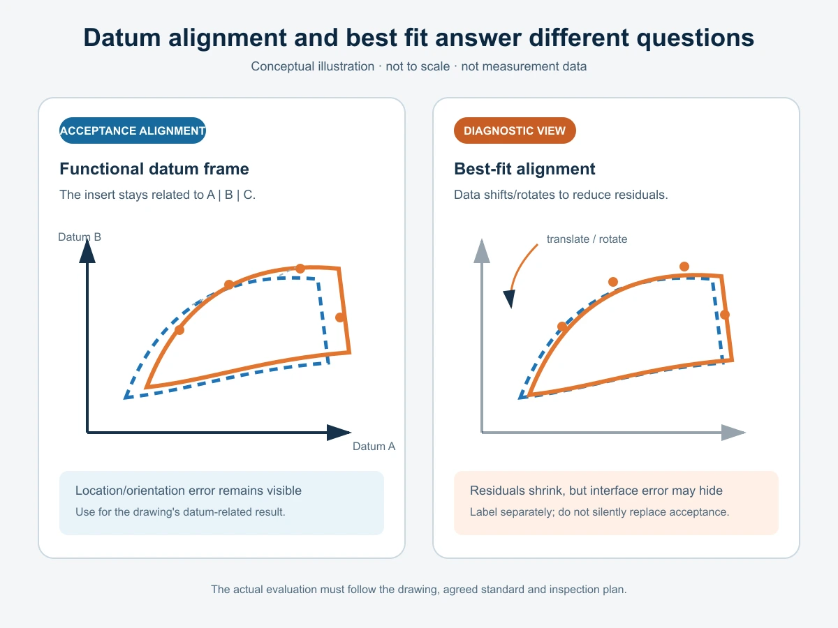
| Question | Functional datum alignment | Best-fit alignment |
|---|---|---|
| What does it represent? | The coordinate frame established by the specified datum system | A mathematical fit chosen to reduce deviations over selected data |
| Primary use | Drawing conformity and functional interface evaluation | Process diagnosis, pattern recognition and comparison |
| Main risk | Poor datum simulation or unstable datum features can corrupt the frame | The fit can conceal location/orientation error relative to mating features |
| Report requirement | Identify datum features, order, modifiers and setup | Identify selected surfaces, fitting criterion and diagnostic-only status |
For example, if the insert seats on datum A, keys laterally from datum B and clocks from datum C, a profile tolerance relative to A|B|C should normally be evaluated in that datum reference frame. A best-fit color map may still help the machinist identify stock or distortion, but it should not replace the specified result on the acceptance report.
The datum features themselves must be measurable and stable. Burrs, texture, edge roll, insufficient feature length, interrupted pads or a clamping method that bends the insert can make the physical realization of the datum inconsistent. This should be resolved at drawing and inspection-planning stage, using the same functional reasoning described in the guide to matching tolerance to function.
Probe access is part of the manufacturing decision
A perfect GD&T scheme can still be difficult to verify if the probe cannot reach the feature with a suitable approach direction. Mold inserts commonly combine deep ribs, narrow slots, small holes, steep draft, shut-offs, undercuts and polished freeform surfaces. Long extensions, star styli or angled heads may improve reach, but they can also change stiffness, qualification needs, collision risk and task uncertainty.
Access review should occur before quotation because it can change both the machining route and the evidence plan. Ask these questions:
- Can the stylus contact the functional region without shanking or touching an adjacent wall?
- Is the stylus ball small enough for the local radius yet sufficiently stiff for the reach?
- Can the probe approach approximately normal to the surface where the measurement strategy requires it?
- Will deep access require a different stylus qualification or an additional setup?
- Does clamping obstruct a datum or deform a thin insert?
- Is the surface in its final machined, EDM, polished or coated state?
- Should a feature be checked by an optical method, gauge or profilometer instead?
For EDM features, inspection planning should also consider corner radii, recast removal and the final finishing state. The mold-insert EDM guide explains why electrode access and surface requirements should be released with the process route rather than added at final inspection.
Freeform profile measurement: more points are not automatically better evidence
A freeform cavity or core surface is often evaluated by comparing measured data with a nominal CAD model. The credibility of that comparison depends on the CAD revision, alignment, coverage, acquisition path, filtering and evaluation rules. A report that says “500 points inspected” does not show whether the points covered the functional surface or clustered in easy-to-reach areas.
Define the strategy by region and risk:
- Critical boundaries: include shut-offs, transition zones, sealing edges and areas that drive part fit.
- High-curvature regions: use sufficient local coverage to reveal form change; avoid interpreting sparse chords as the actual surface.
- Edges and discontinuities: specify intentional exclusion distances when probe geometry or burr risk makes edge data unreliable.
- Scan paths: identify path direction, line spacing, speed and any filtering or smoothing that affects reported deviations.
- Constructed features: record the point selection and fitting rule used to create planes, cylinders, circles or intersections.
- Unreachable regions: identify them explicitly and assign an alternative method instead of reporting the accessible subset as the whole feature.
Software is part of the measurement system. NIST notes that fitting, filtering, calibration and software behavior can contribute to measurement uncertainty and error.[6] The report therefore should not be treated as method-neutral merely because it was generated automatically.
Surface texture needs a separate plan. A CMM point cloud does not replace Ra/Rz evaluation, direction-of-lay review or cosmetic acceptance. When roughness matters, coordinate the profile result with the inspection state and method in the mold insert surface-finish guide.
Machine performance, task uncertainty and the acceptance decision are different things
ISO 10360-2:2009 specifies acceptance and reverification tests for Cartesian CMMs used for linear dimensional measurements with contacting probes in discrete-point mode.[3] Those tests are important evidence about machine performance. They are not, by themselves, a complete uncertainty statement for every feature, stylus, orientation, temperature and evaluation strategy used on a particular mold insert.
NIST’s guidance on CMM measurement uncertainty describes the interaction between workpiece tolerance and measurement uncertainty and identifies multiple factors that affect CMM results.[5] Other NIST work highlights positioning and straightness, probing response, motion, environmental stability, procedure and thermal effects as relevant sources.[7] This distinction matters commercially: a machine specification is not automatically the uncertainty of the reported profile or position value.
For a tight characteristic, the supplier and buyer should agree how conformity will be decided near the tolerance boundary. ISO 14253-1:2017 establishes decision rules that take measurement uncertainty into account when verifying conformity or nonconformity.[4] Depending on the contract, the rule may create an uncertainty zone or guard band rather than treating every displayed value inside the nominal tolerance as automatically accepted.
“The CMM passed its performance verification,” “the measurement program repeats,” and “this characteristic is proven conforming with an agreed decision rule” are related, but they are not equivalent.
Repeatability tests only show variation under the tested repeated conditions. They may not capture datum re-establishment, different operators, thermal change, stylus changes, workpiece variation or systematic error. Calibration and traceability are also not substitutes for task-specific uncertainty: traceability connects results to references through a documented chain, while uncertainty describes the doubt associated with the result.
Temperature deserves explicit treatment. Mold steels expand and contract, and a small insert can still contain a critical feature where thermal difference is significant relative to tolerance. State the inspection temperature or conditioning method, material information used for compensation and whether the workpiece had time to stabilize. Avoid automatic compensation based on an assumed coefficient when the material and heat-treatment state are uncertain.
Use D-A-T-A to release CMM inspection evidence
The D-A-T-A model converts a vague “full CMM report required” request into four auditable decisions.
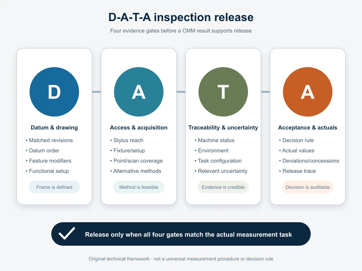
D — Datum and drawing revision
Freeze the 2D drawing, CAD model and revision. Identify the datum system for every reported characteristic and resolve any conflict between the drawing and model-based definition. Record how the datum features will be physically contacted or simulated. If the inspection program uses a temporary machining alignment, keep it separate from the functional acceptance alignment.
A — Access and acquisition strategy
Review stylus access, setup count, clamping, point distribution and scan coverage. Mark inaccessible or high-risk regions before quotation. For each CTQ, identify whether the result comes from discrete points, scanning, construction, comparison with CAD or another method.
T — Traceability and task-specific uncertainty
Reference the measuring system, calibration or verification status, environmental conditions and relevant uncertainty or capability evidence. For critical features, ensure that the evidence reflects the actual stylus, reach, orientation, program and feature—not only a brochure value for the machine.
A — Acceptance rule and actual results
State the decision rule in the purchase agreement or inspection plan. Report actual values and units, not only pass/fail color. Identify deviations, rework state and any approved concessions. A summary page can be useful, but it should link each CTQ back to an individual result and the drawing callout.
Worked example: one insert, three critical characteristics
Consider a hardened cavity insert with a ground seating face, two locating sides, a contoured forming surface and a small cooling-related bore. The drawing establishes datum A on the seating face, datum B on the primary locating side and datum C on the clocking side.
CTQ 1 — installed height from datum A: this characteristic should be evaluated from the functional seating datum. Cleanliness, flatness, fixturing and the contact distribution used to establish A matter. A best-fit of the overall insert would be inappropriate because it could shift the seating relationship that controls assembly height.
CTQ 2 — profile of the forming surface relative to A|B|C: the program should use the specified datum reference frame, the correct CAD revision and a coverage plan for the full functional region. A second best-fit color map may be provided to diagnose machining stock, but it must be labeled separately. The report should state scan paths or point zones, exclusions and the evaluation rule.
CTQ 3 — small bore position: first confirm that a suitable stylus can enter without shanking and that enough bore depth is available to establish the feature. If contact probing cannot produce defensible evidence, an optical method, calibrated pin or another agreed method may be better. The method must still relate the bore to A|B|C.
These three CTQs should not be reduced to “CMM 100% inspection.” They require different access, construction and uncertainty considerations. The resulting report package should preserve the common drawing revision and datum logic while documenting the method used for each characteristic.
When a CMM is not the complete answer
| Requirement | Likely primary method | Planning caution |
|---|---|---|
| Datum-related location, orientation or freeform profile | CMM contact points or scanning | Define alignment, access, coverage, software evaluation and uncertainty |
| Very small radius, narrow slot or fine edge detail | Optical system, microscope, replica or section method | Check optical edge definition, magnification, calibration and part orientation |
| Surface roughness or lay | Contact or optical profilometer | State parameter, cutoff/filter, direction and surface state |
| Simple production fit or limit condition | Functional gauge, plug/ring gauge or comparator | A gauge can be efficient but may not diagnose the cause of failure |
| Burr, edge break, recast layer or cosmetic defect | Visual/microscopic inspection plus an agreed reference | Define lighting, magnification, location and acceptance sample |
A hybrid plan is often more credible than forcing every callout onto one instrument. The purpose is to choose a method that can access and resolve the characteristic with acceptable uncertainty, then connect the results into one traceable release package.
CMM inspection RFQ and report checklist
Add this information to the broader precision mold component RFQ package:
- matched 2D drawing and 3D CAD revisions, with units and governing document identified;
- CTQ list with characteristic IDs, tolerances, datum references and functional consequence;
- material, heat-treatment state and final machining/EDM/polishing condition at inspection;
- datum feature accessibility and any required fixture or simulated datum;
- preferred or prohibited alignment methods, with best fit separated from acceptance;
- point zones, scan paths, coverage requirements and edge exclusions for profiles;
- small-feature, deep-access and undercut review with alternative methods where needed;
- temperature/conditioning and part-cleaning requirements;
- measurement uncertainty or agreed capability evidence for tight characteristics;
- contractual decision rule, guard band or uncertainty-zone treatment;
- required actual-value report, color map, raw data or program information;
- machine identification, calibration/verification status and report traceability;
- nonconformance, rework, concession and reinspection documentation rules.
For replacement components, also specify pocket datums, installed height and interface evidence from the replacement mold insert guide. For hardened inserts, align the inspection stage with the steel and heat-treatment route so that results are not taken from an irrelevant pre-finish condition.
Is a CMM report enough to approve a mold insert?
Only if it covers the applicable drawing characteristics with the correct datum system, suitable methods, adequate uncertainty and the agreed acceptance rule. Surface roughness, visual defects, hardness, material certification and functional fitting may require separate evidence.
Should the supplier use datum alignment or best fit?
Use the drawing’s specified datum reference frame for conformity unless the contract explicitly defines another rule. Best fit can be supplied as additional diagnostic information, but it should be labeled and should not silently replace datum-based acceptance.
How many points should be used for a freeform profile?
There is no universal number. Define coverage from surface size, curvature, tolerance, functional zones, probe geometry, scan strategy and uncertainty. A smaller, well-distributed plan can be more informative than a larger point count concentrated in easy regions.
Does the CMM’s published accuracy prove it can measure the tolerance?
No. Published maximum permissible error or verified machine performance is an important input, but the task result also depends on probe configuration, reach, feature geometry, alignment, environment, software, sampling and procedure. Review the uncertainty or capability for the actual measurement task.
What should happen when a measured value is close to the tolerance limit?
Apply the decision rule agreed in the contract or inspection plan. ISO 14253-1 addresses conformity decisions that account for measurement uncertainty; the measured value alone may not support an unqualified pass when it is near a specification limit.
Can CMM inspection verify Ra or Rz surface roughness?
A conventional CMM inspection is not a substitute for a roughness measurement. Use the specified contact or optical surface-texture method and report its parameter, filter/cutoff, direction and surface condition.
What should a buyer send for a CMM feasibility review?
Send the current drawing/model revision, datum scheme, CTQ list, material and heat-treatment state, final surface condition and required evidence. Use Huicheng’s contact page to request a machining and inspection feasibility review before the final quotation package is frozen.
References
- ISO 5459:2024, Geometrical product specifications — Geometrical tolerancing — Datums and datum systems — official scope and current standard status.
- ISO 1101:2017, Geometrical product specifications — Geometrical tolerancing — symbol language and interpretation rules for geometrical specifications.
- ISO 10360-2:2009, Acceptance and reverification tests for CMMs used for measuring linear dimensions — performance testing scope for applicable Cartesian CMMs.
- ISO 14253-1:2017, Decision rules for verifying conformity or nonconformity with specifications — treatment of measurement uncertainty near specification limits.
- NISTIR 5170, Measurement Uncertainty Considerations for Coordinate Measuring Machines — task factors and the relationship between uncertainty and workpiece tolerance.
- NIST, Should You Be Concerned with Software Measurement Uncertainty? — software fitting, filtering and related sources of measurement error.
- NIST, Accuracy and Versatility of the NIST M48 Coordinate Measuring Machine — examples of machine, probe, motion, environmental and procedural influences.
Engineering note: This article is a planning framework, not a measurement procedure, uncertainty budget or contractual decision rule. The drawing, applicable standard editions, inspection method and acceptance criteria must be agreed for the actual component and purchase order.