Steel-safe mold insert design is a directional correction strategy—not a request to “leave extra steel everywhere.” For every uncertain molded feature, the team must identify the mold surface that creates it, decide which future part change is most likely, and confirm that the change can be made by controlled metal removal without damaging a related fit, shut-off, draft or surface requirement.
This guide gives mold designers, tooling engineers, buyers and quality teams a practical method for releasing steel-safe precision mold inserts. It also explains why a resin shrinkage value is an engineering input rather than acceptance proof, and how controlled mold-trial data should govern the final correction.
A feature is steel-safe only when its expected correction can be achieved by removing a defined mold surface in a defined direction. Record the critical part result, affected mold surface, intentional reserve, machining limit and trial evidence required to release the final dimension.
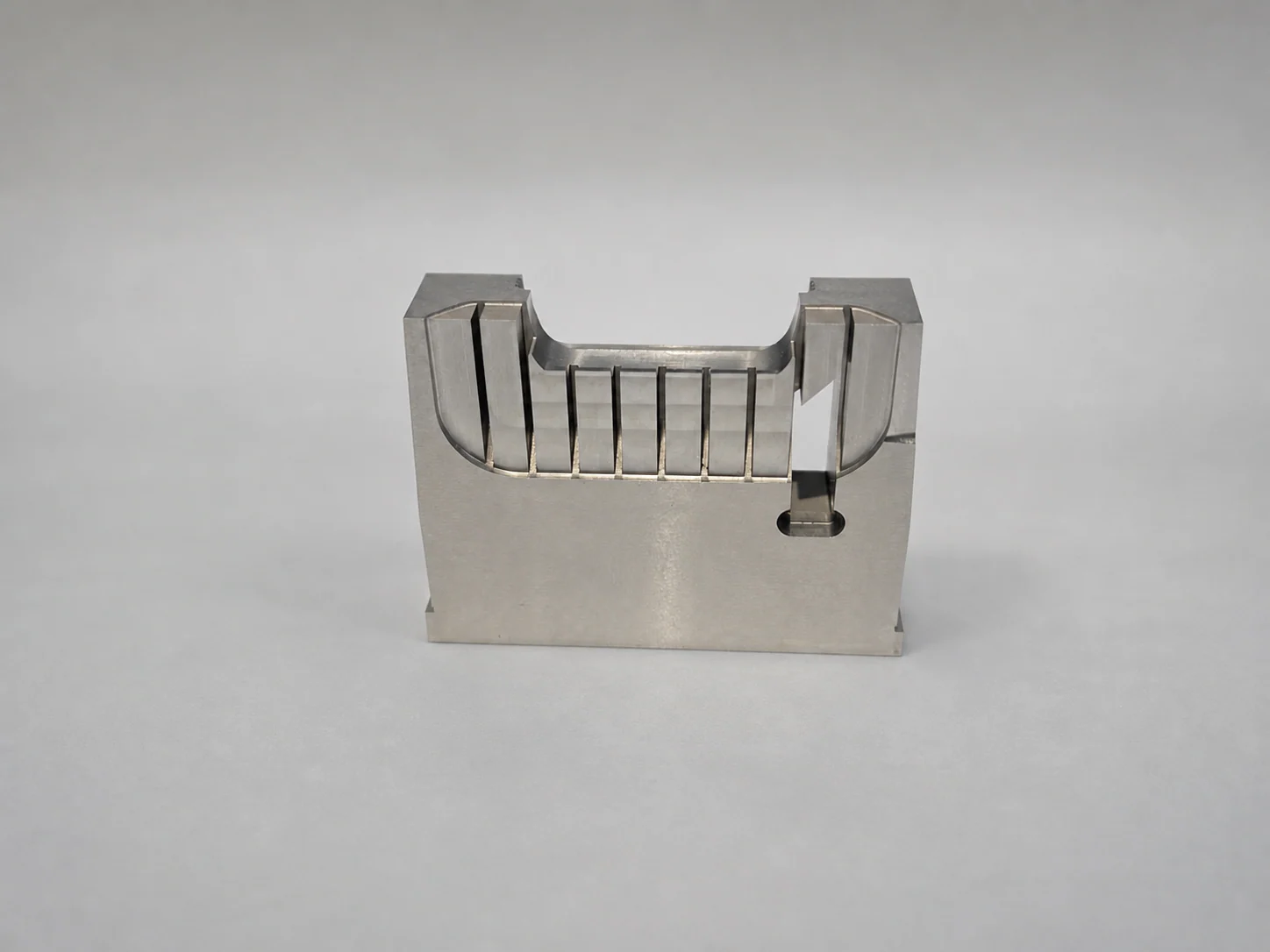
What “steel-safe” should mean on a real drawing
In moldmaking, “steel-safe” commonly describes a condition that preserves a future correction by removing metal from the tool. Protolabs uses the same basic idea: plan the initial mold so that later changes can be achieved by metal removal, which is generally easier than adding metal.[1] The useful principle is simple; applying it safely is not.
A note such as “dimensions steel-safe for T0” is incomplete because it does not answer five questions:
- Which molded dimensions are intentionally offset, and which are already final?
- Which cavity, core, slide, lifter or shut-off surface controls each result?
- In which direction may the molded feature need to move after the trial?
- How much metal may be removed, from which datum and by which finishing process?
- What measured trial evidence authorizes the correction and stops further removal?
Leaving unspecified stock on every surface can create a tool that is neither functionally correct nor easy to finish. It can change wall thickness, draft, vent depth, shut-off contact, insert fit, edge strength, texture allowance and cooling distance. Steel-safe intent therefore belongs in the drawing and trial plan feature by feature.
The same discipline used to match tolerance to function should be applied here: begin with the part requirement, datum system and failure consequence. Only then decide whether a deliberate pre-trial offset is justified.
Map part change to the mold surface before reserving steel
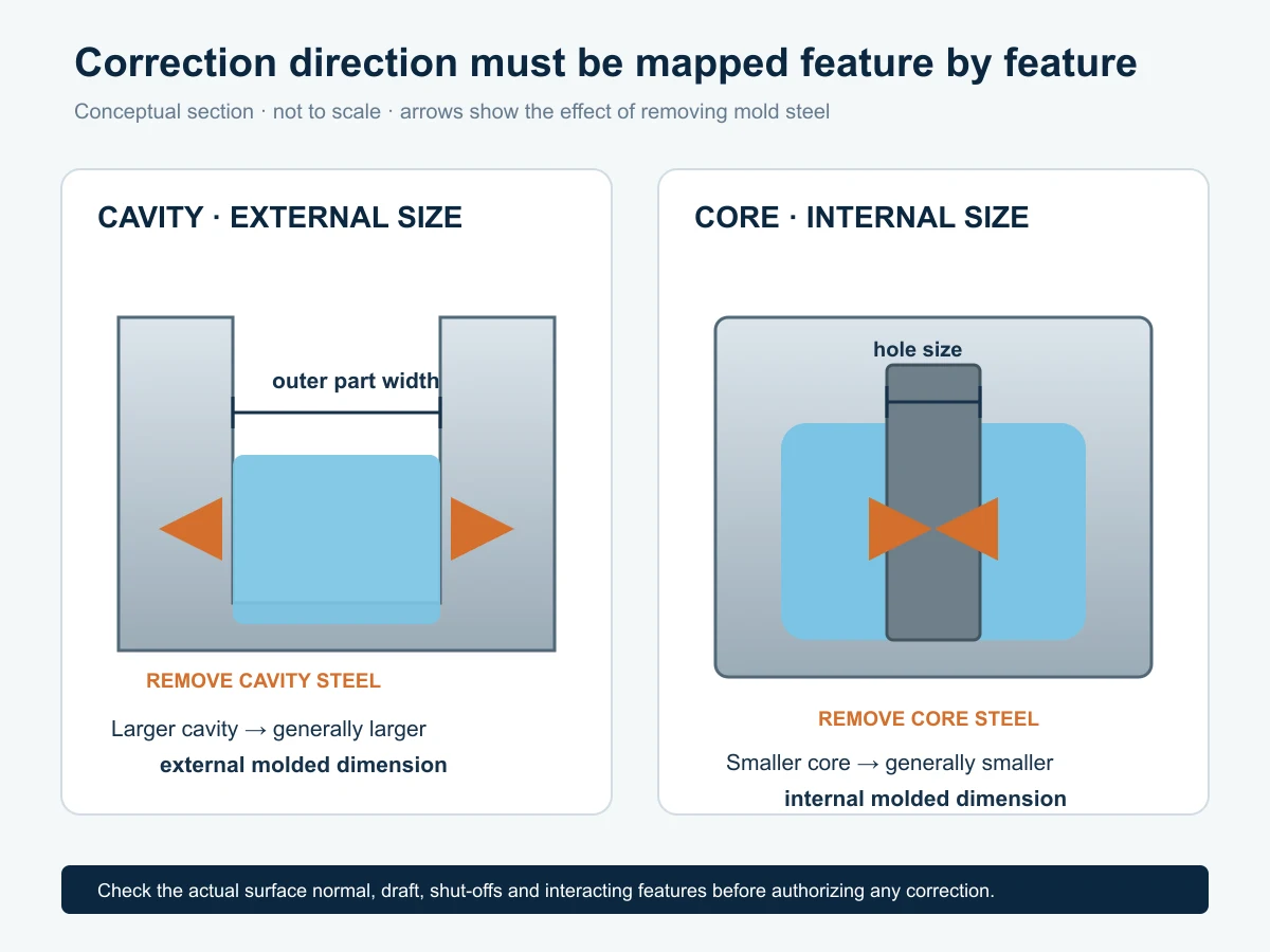
Always reason through three links: molded-part dimension → forming surface → effect of removing metal. A general slogan such as “more steel means less plastic” fails when the controlling surface changes from a cavity to a core.
| Part result | Typical controlling mold surface | Effect of removing steel | Steel-safe question |
|---|---|---|---|
| External width or boss OD | Cavity wall | Enlarges the cavity and generally increases the external part dimension | Is the safe initial condition a deliberately smaller external feature that may be opened later? |
| Hole ID or internal opening | Core OD | Reduces the core and generally decreases the molded internal dimension | If the hole may need to become smaller, can the core start larger and be reduced? |
| Wall thickness | One or both opposing surfaces | Depends on which surface is moved and its local normal | Which functional side may move without changing the datum, fit or appearance? |
| Shut-off or parting-line condition | Mating cavity/core, slide or lifter faces | May alter contact, flash risk, witness line and component motion | Can one face be corrected while preserving shut-off angle, support and preload? |
For complex freeform geometry, evaluate the correction as a local surface offset or vector—not merely an X, Y or Z change. A nominal offset along a surface normal can also shift an edge, change draft, thin a shut-off or break continuity with an adjacent insert. The correction package should identify all affected surfaces and protected boundaries.
Some changes cannot remain steel-safe in one fixed insert. If likely trial outcomes include both increasing and decreasing the same molded dimension, a replaceable core, shim strategy or deliberately sacrificial detail may be more controllable than assuming weld repair will be acceptable. That choice should be made before tool steel, hardness, texture and appearance requirements make rework harder.
Shrinkage prediction is an input—not the final correction value
ISO 294-4:2018 defines methods for determining molding and post-molding shrinkage of thermoplastic test specimens, including directions parallel and normal to melt flow.[2] That is useful standardized material evidence, but a test-specimen result is not automatically the correct compensation for every dimension on a production part.
The BASF Ultraform POM brochure, for example, explains that shrinkage depends on geometry and wall thickness as well as mold temperature, melt temperature, holding pressure, injection speed, gate position and gate size, and that exact prediction can be difficult.[4] The lesson extends beyond one resin family: treat the material data as a starting range under stated conditions, then evaluate the actual part, flow path and process.
Simulation can reduce uncertainty, but it still depends on its inputs and model. Autodesk’s Moldflow documentation notes that warpage analysis uses fill, pack and cooling results, and that packing conditions, gate/feed representation and cooling effects matter.[5] Its shrinkage model documentation also identifies volumetric shrinkage, crystallization, orientation and mold restraint as contributors, with possible differences parallel and perpendicular to the principal direction.[6]
Before using trial measurements to cut steel, control or record at least:
- approved resin grade, filler, colorant, moisture or preconditioning state and material lot;
- melt and mold temperatures, injection/transfer point, pack pressure and time, cooling time and cycle stability;
- gate condition, cavity number and any imbalance or visible process defect;
- part conditioning time, temperature and humidity before measurement;
- measurement fixture, datum setup, method, sample size and repeatability;
- whether the observed error is consistent, directional or cavity-specific.
ISO 20457:2026 likewise frames molded-part dimensional control as a system affected by material, part design, tool layout and processing. It calls for agreed molding-shrinkage handling and function-related tolerances rather than pretending that one compensation number can remove all process-induced variation.[3]
Do not machine a permanent tool correction from an unstable trial. First establish that the process is capable of producing repeatable parts under the agreed material, machine, tool-temperature and conditioning conditions.
Use C-A-S-T to release each steel-safe feature
The C-A-S-T model turns an informal tooling request into a controlled engineering record.
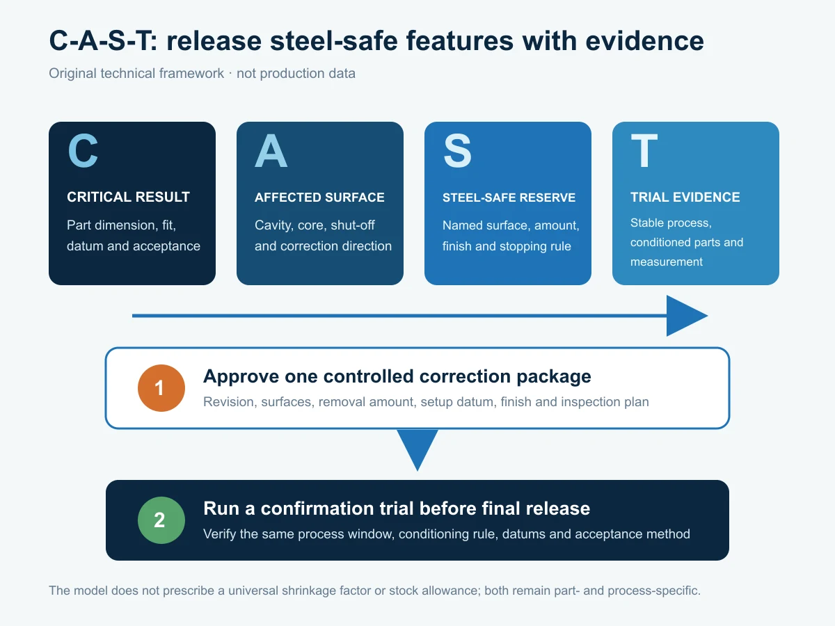
C — Critical part result
Name the molded feature, nominal value, tolerance, datum relationship and functional reason. State the trial-stage acceptance rule separately from the final part rule if the feature is intentionally offset. A vague “steel-safe” flag must never conceal what the T0 part is expected to measure.
A — Affected mold surface and direction
Identify the insert, surface IDs, local correction direction, setup datum and protected adjacent geometry. Include the mating insert or moving component when the correction changes a shut-off, slide travel, lifter release or parting-line condition. For replacement tooling, connect this map to the pocket, installed height and functional interface checks in the replacement mold insert guide.
S — Steel-safe reserve and stopping rule
State the intentional offset or removable stock for the named surface, along with the permitted machining process and final finish allowance. The amount is part-specific. It must consider predicted correction, process variation, machining control, surface finish, polishing or texture stock, edge condition, hardness and available metrology. Avoid a company-wide default applied to every insert.
Also define a stop: maximum metal removal, minimum remaining condition, or a “no correction without engineering approval” boundary. Irreversible work should be released by drawing revision or an identified correction instruction, not by a chat message or a marked-up screenshot with no traceability.
T — Trial evidence
Specify the trial number, process record, material condition, sample identification, conditioning rule, measurement report and approval owner. A single part can reveal a defect, but it rarely demonstrates a stable mean and variation. The sample plan should match the risk, number of cavities and decision being made.
A controlled trial-to-correction workflow
- Freeze the decision inputs. Release the current part drawing, insert model, resin grade, CTQ list, datum scheme, expected process window and steel-safe feature register.
- Review correction feasibility before machining. Confirm that metal removal can reach the required surface without violating draft, cooling, venting, texture, edge strength, fitting or the steel and hardness route.
- Machine and inspect the pre-trial condition. Report both final features and deliberate offsets. This prevents the trial team from treating an intentional condition as a manufacturing nonconformance.
- Run T0/T1 under recorded conditions. Stabilize the process, identify cavities and preserve representative samples. Do not hide a process problem by immediately cutting the tool.
- Condition and measure parts by the agreed rule. Use the functional datums and separate repeatability, cavity-to-cavity difference and mean offset.
- Classify the cause. Decide whether the response belongs to the molding process, tool geometry, part design/material or the measurement system.
- Approve one correction package. Record revision, affected surfaces, removal amount, setup, machining method, finish requirement and inspection points.
- Correct and re-inspect the insert. Verify the tool change itself before the confirmation trial. For EDM surfaces, define recast removal and final finish using the mold-insert EDM selection guide.
- Run a confirmation trial. Reproduce the agreed process and measurement conditions, then release the final dimension only when the evidence meets the acceptance rule.
Texture and high-cosmetic finishing deserve a deliberate gate. If possible, confirm geometry before applying a finish that is difficult to blend after local correction. When the forming surface must be refinished, state the final Ra/Rz or visual acceptance zone and method; the mold insert surface-finish guide explains why process state and measurement direction matter.
Should the correction belong to process, tool or part design?
| Evidence pattern | First investigation | Why immediate steel removal is risky |
|---|---|---|
| Dimension drifts with pack pressure, temperature or cooling time | Process stability and acceptable window | A geometry correction may compensate one setting and fail at another |
| Stable mean offset across repeat trials and conditioned samples | Tool correction direction and magnitude | Still requires interaction and machining-limit review |
| One cavity differs while the others track together | Cavity geometry, gate, cooling, venting and local measurement | A global correction would damage acceptable cavities |
| Feature meets size but fails assembly or load | Part design, datum definition and functional tolerance | Changing nominal size may mask a specification problem |
| Measurement changes by fixture, operator or conditioning time | Measurement system and conditioning rule | The tool could be cut to measurement noise |
The goal is not to avoid tool correction. It is to make the correct irreversible change after reversible sources of variation have been understood.
Worked example: one width, one hole and one shut-off
Consider a molded housing with a critical external width, a locating hole and a side-action shut-off. The team expects the resin and rib layout to create some dimensional uncertainty, but it does not yet have representative production-trial data.
External width: the two cavity walls control the result. If the likely correction is to make the molded width larger, the initial cavity can be released deliberately small within a stated trial rule, because controlled removal from the cavity walls can open it. The correction instruction must state whether both walls move symmetrically or one datum-side wall remains fixed.
Locating hole: the core controls the hole. Removing metal from the core makes the core smaller and generally makes the molded hole smaller—not larger. If the expected correction is to reduce hole size, an intentionally larger core may be steel-safe. If the hole may need to increase, the design may require a replaceable core, an alternate initial strategy or approved metal addition; the cavity rule cannot simply be copied.
Side shut-off: the slide and fixed insert create both the part edge and a sealing interface. Removing metal to change the edge may reduce shut-off contact or alter flash risk. The release must protect the shut-off angle and support length, and may require coordinated work on a replaceable detail rather than a simple surface offset.
The trial report should therefore contain three separate decisions. “Adjust shrinkage by 0.4%” would be inadequate because the features are formed by different surfaces, respond in different directions and have different functional risks. A steel-safe register makes those differences visible before the cutter touches the tool.
Steel-safe mold insert RFQ and drawing checklist
Add this register to the broader precision mold component RFQ package:
- current 2D drawing and 3D model with matching revisions;
- molded resin, filler/colorant, supplier data and expected conditioning;
- critical part dimensions, functional datums and assembly consequences;
- cavity/core/slide/lifter surface map for each uncertain feature;
- desired future correction direction from the part perspective;
- intentional pre-trial offset or removable stock, with no universal default;
- protected draft, shut-off, edge, cooling, vent and texture conditions;
- insert steel, hardness and permitted finishing process;
- pre-trial insert inspection report showing actual intentional offsets;
- trial process record, material lot, cavity/sample identification and conditioning rule;
- measurement method, datum setup, sample plan and approval owner;
- correction authorization, stopping rule and confirmation-trial requirement.
What is the difference between steel-safe and machining allowance?
A machining allowance is stock reserved for a planned manufacturing step, such as grinding after heat treatment. A steel-safe reserve is a deliberate functional offset kept until trial evidence determines whether and how far to correct the molded result. They may occupy the same surface, but they have different purposes and release rules.
How much steel-safe stock should a mold insert have?
There is no universal value. The amount depends on the uncertain part result, resin/process sensitivity, feature scale, tolerance, simulation and historical evidence, insert material and hardness, finishing method, texture/polish stock, measurement capability and the cost of being wrong in either direction.
Does “steel-safe” always mean the first molded part should be smaller?
No. It depends on whether a cavity, core or another surface forms the dimension. Removing cavity steel can increase an external part size, while removing core steel generally decreases an internal opening. State the intended part direction explicitly.
Can simulation replace a mold trial?
Simulation can identify risk and support the initial compensation, but its result depends on material data, mesh/model choices, process inputs, gate/feed representation and cooling assumptions. Final acceptance should use controlled physical parts measured under the agreed conditions.
Can welding restore a feature if too much steel is removed?
Sometimes, but it is not a neutral reset. Welding can affect hardness, distortion, polish/texture appearance, corrosion behavior and local life. The material, heat-treatment condition, cosmetic requirement and repair procedure must be reviewed before treating welding as the backup plan.
What should a supplier receive before quoting?
At minimum: matched drawing/model revisions, critical part features and datums, insert interfaces, resin and trial assumptions, steel-safe surface register, material/hardness/finish requirements and inspection evidence. Send these through Huicheng’s contact page for a machining and inspection feasibility review.
References
- Protolabs, “How to Plan for Design Changes Without Breaking the Bank” — practical definition and examples of steel-safe mold changes.
- ISO 294-4:2018, Plastics — Injection moulding of test specimens — Part 4 — standardized molding- and post-molding-shrinkage determination.
- ISO 20457:2026, Plastics moulded parts — Tolerances and acceptance conditions — dimensional influences, function-related tolerances and shrinkage agreement.
- BASF, Ultraform product brochure — material-specific discussion of geometry and processing effects on shrinkage.
- Autodesk Moldflow Insight Help, Preparing a model for Warp analysis — fill/pack/cooling inputs and model considerations.
- Autodesk Moldflow Insight Help, Residual strain shrinkage prediction — volumetric, crystallization, orientation and restraint effects.
Engineering note: This article provides a decision framework, not a universal shrinkage factor, stock allowance or tool-correction instruction. Final values must be selected for the actual resin, part, mold, process, trial evidence and contractual acceptance plan.